This will document my World War II US Army Signal Corps Impression. Now, per Chad Phillips, who is an expert in World War II Signal Corps impressions, research, and documentation in the WW2 Signal Corps Facebook group, indicated that for a basic Lineman and Groundsman Impression, you should have the following –
Lineman
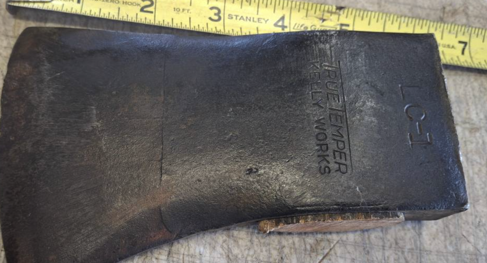
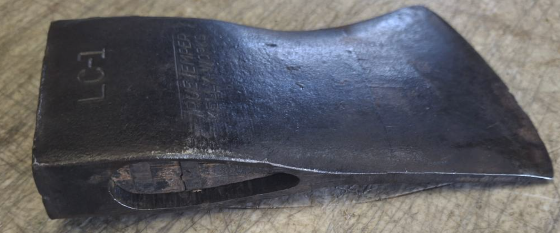
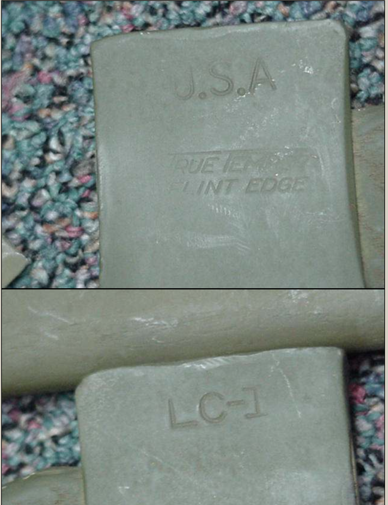
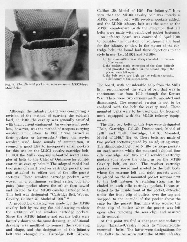
LC-1 Axe: LC stands for Line Construction, and would say LC-1 on it, and might say “True Temper Kelly Works” or “True Temper Flint Edge”.
Kelly Axe Manufacturing Company produced axes but was bought by American Fork and Hoe in 1930. They then began the True Temper brand of axes. AFH likely kept the name “Kelly Works” on some of the “True Temper” brand of axes. For a look at the 1938 American Fork and Co. catalog, see: True Temper Tools General Catalog 1R.
The LC-1 Axe Handle may be around 18 inches in total length. 2 inches inside the axe head, and 16 inches showing. The handle may have been painted green and installed with a few splits inside the head. The green paint might be a field modification as “load out” images that show all the tools on display; the ax is left unpainted, suggesting the paint came in the field. Indeed, the original ones look glossy black and dark blue.
A close-up of the LC-1 Ax head in this image shows that the handle is painted green. If you wanted to paint it green, Krylon 4293 (which seems to be found only at Lowe’s) would be a good color to use. Midwest Military sells a Signal Corps green color, but it’s unclear if it’s the right color green.
The handle likely came in different styles, such as straight. Though images that show items on display show that the handle is slightly curved.
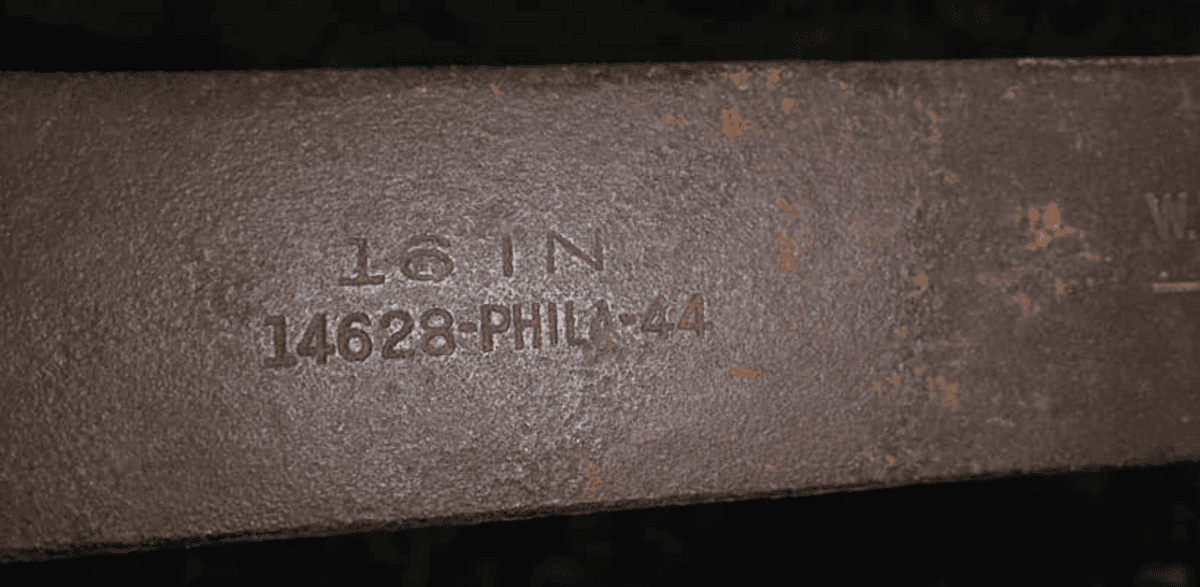
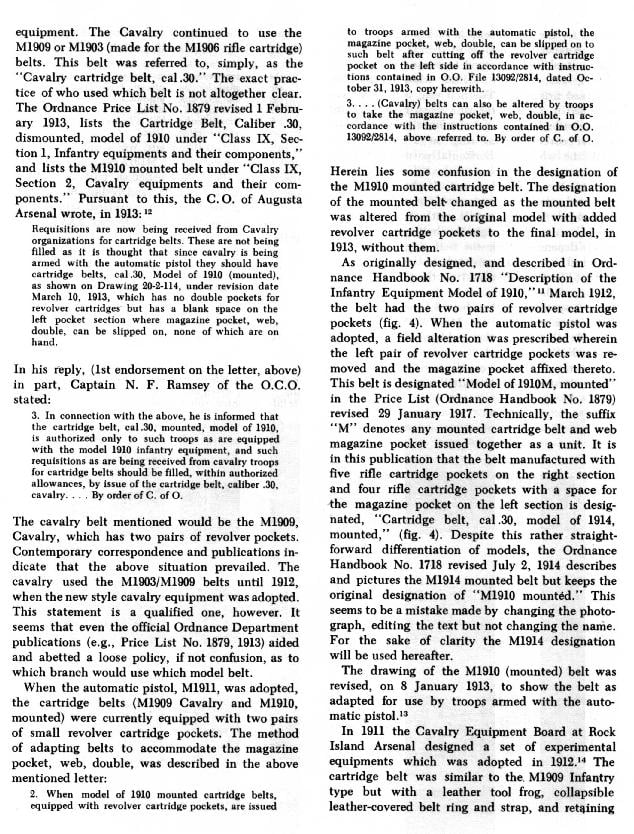
LC-23A and LC-23B belt w/strap [late ’44 date]: Came in two styles. A canvas and a leather version. Also came in multiple sizes. LC-23-A is likely the canvas version. LC-23-B is the leather version. This matches the EEa and EEb phone designs as well.
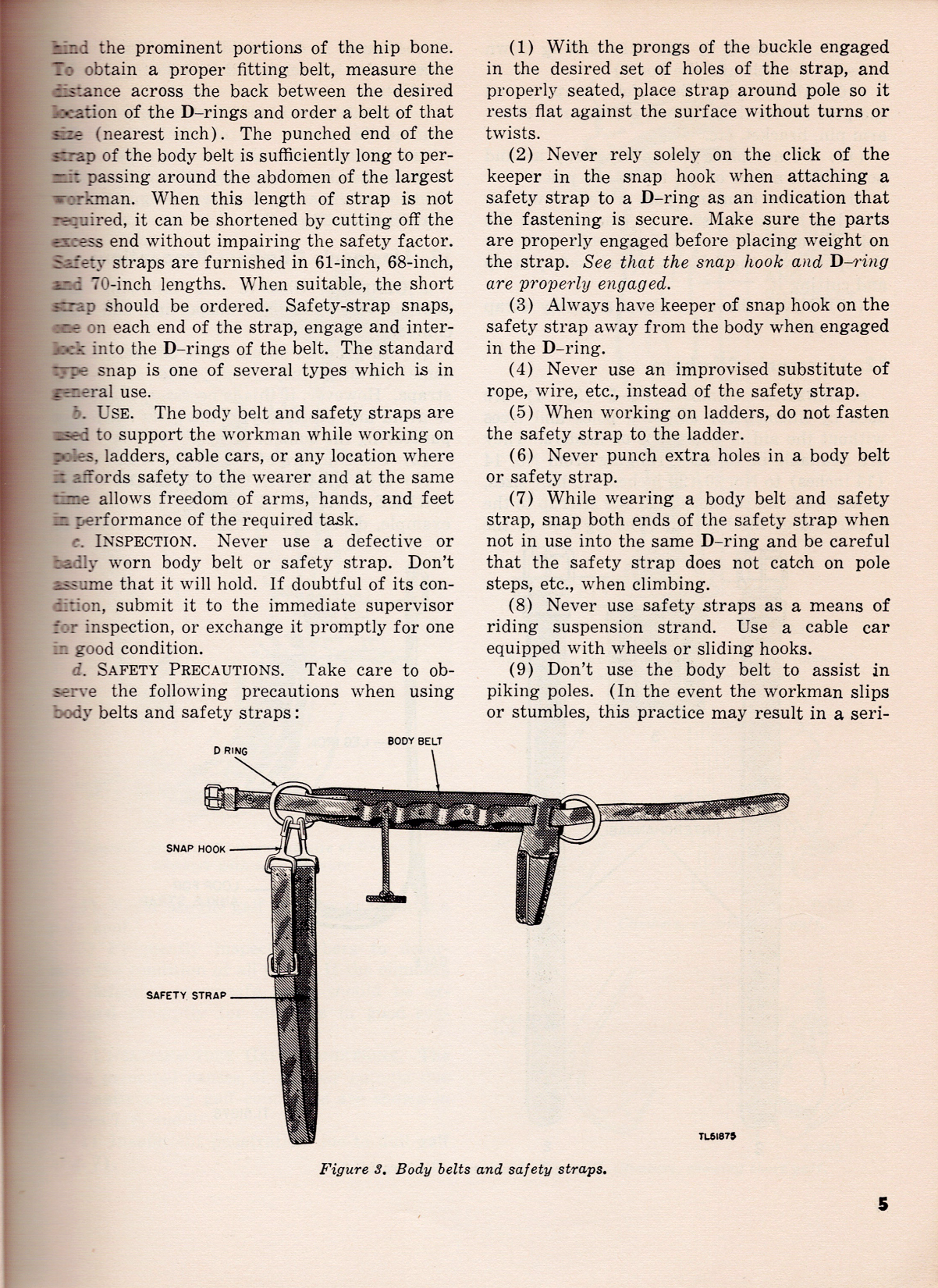
According to the May 1947 TM 11-372 field manual, the belt is sewn with linen thread and locked-stitched with copper rivets. It’s tested up to 1,500 lbs. The belts come in D-ring sizes of 18, 20, 22, 24, 26, 28, and 30. Size is determined in inches between the D-rings. Comfort with the belt is dependent on the right size in proportion to the hip bone. Each belt also had a safety strap, which was used to wrap around the pole.
To obtain a proper fitting belt, measure the distance across the back between the desired location of the D-rings and order a belt of that size (nearest inch). The punched end of the strap of the body belt is sufficiently long to permit passing around the abdomen of the largest workman.
To obtain a proper fitting belt, measure the distance across the back between the desired location of the D-rings and order a belt of that size (nearest inch). The punched end of the strap of the body belt is sufficiently long to permit passing around the abdomen of the largest workman. When this length of strap is not required, it can be shortened by cutting off the excess end without impairing the safety factor. Safety straps are furnished in 61-inch, 68-inch, and 70-inch lengths. When suitable, the short strap should be ordered.
Body Belts and Safety Straps for the LC-23 A and B
Measuring LC-23 A and B
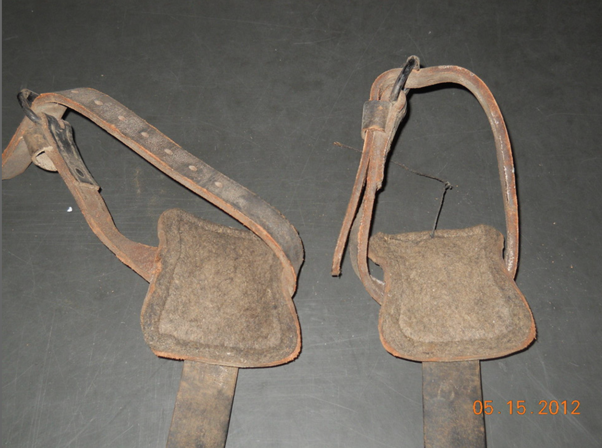
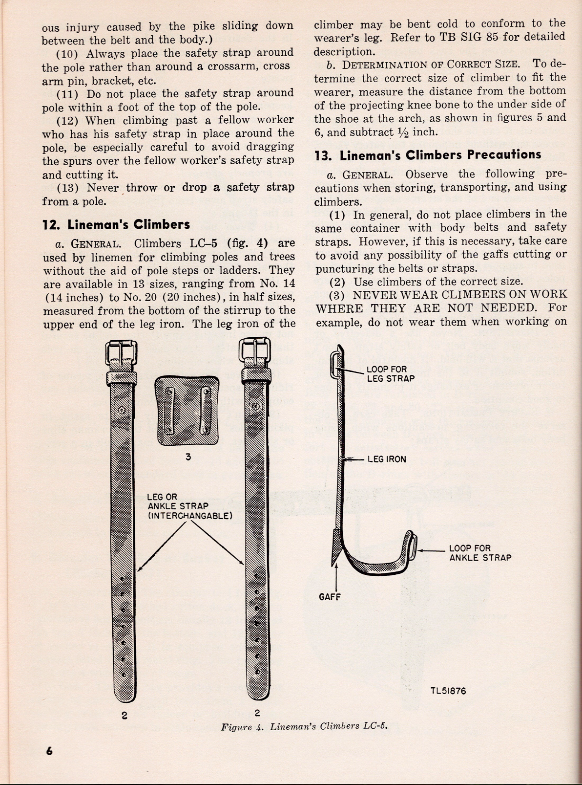
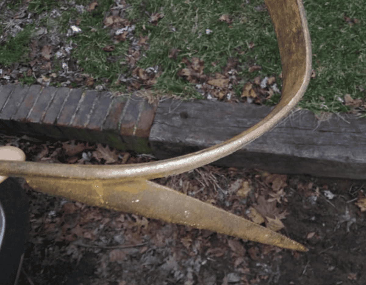
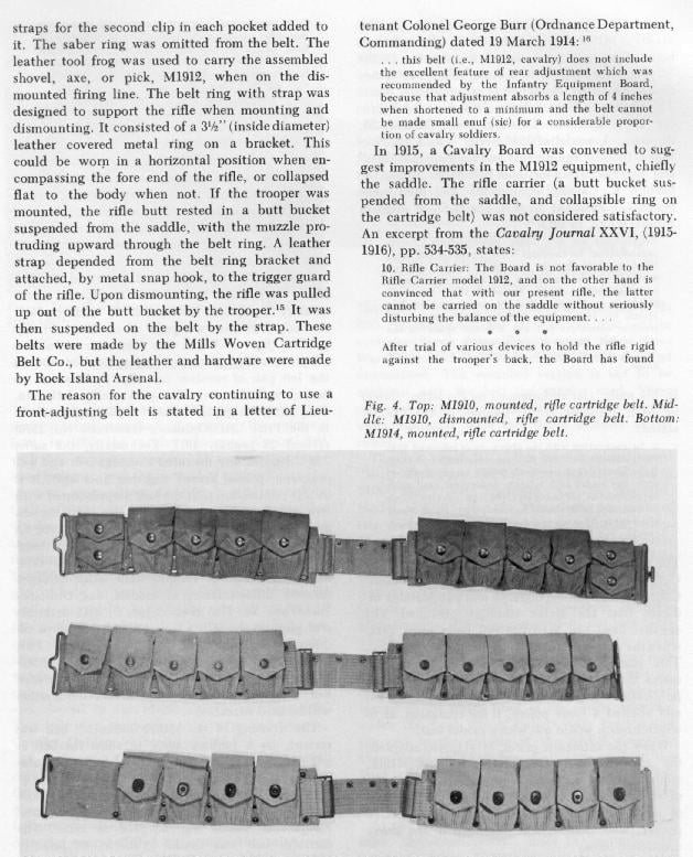
LC-5 Climbers: The spikes are called gaffs. Included with the climbers are a leather strap and a coarse cloth square pad, SAE F3 Felt.
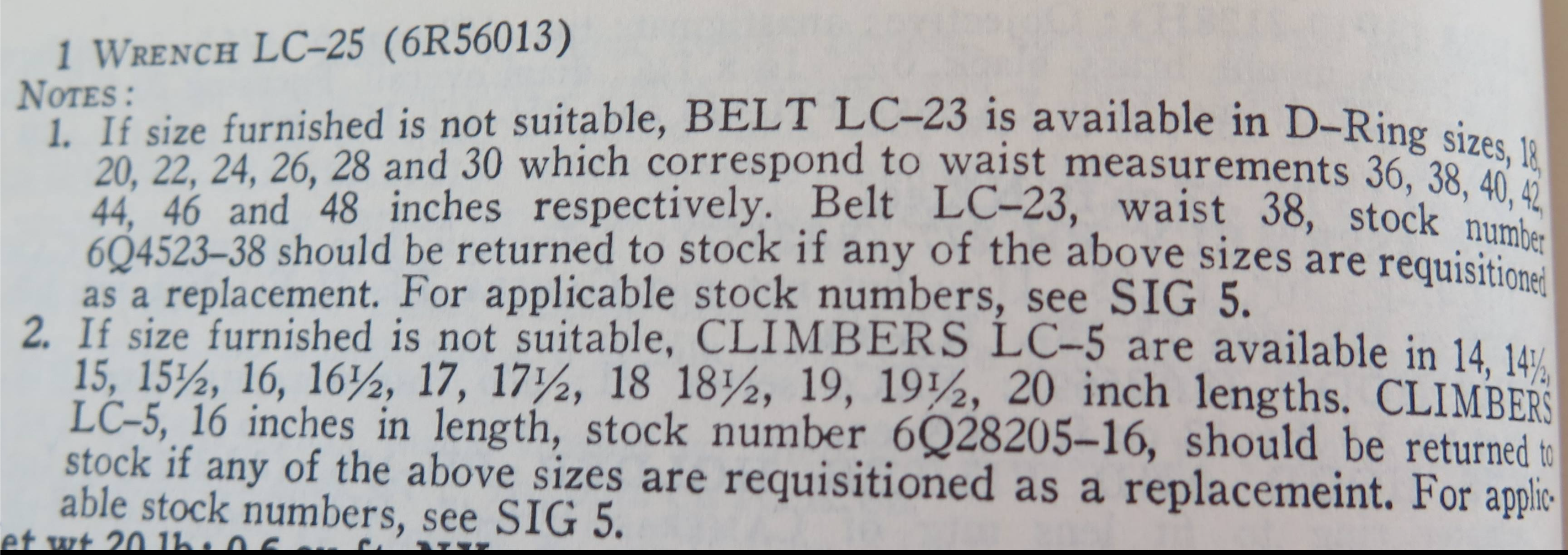
They came in multiple sizes; see the notes section of the image below, which describes the sizes for the LC-23 belt and the LC-5 climbers.
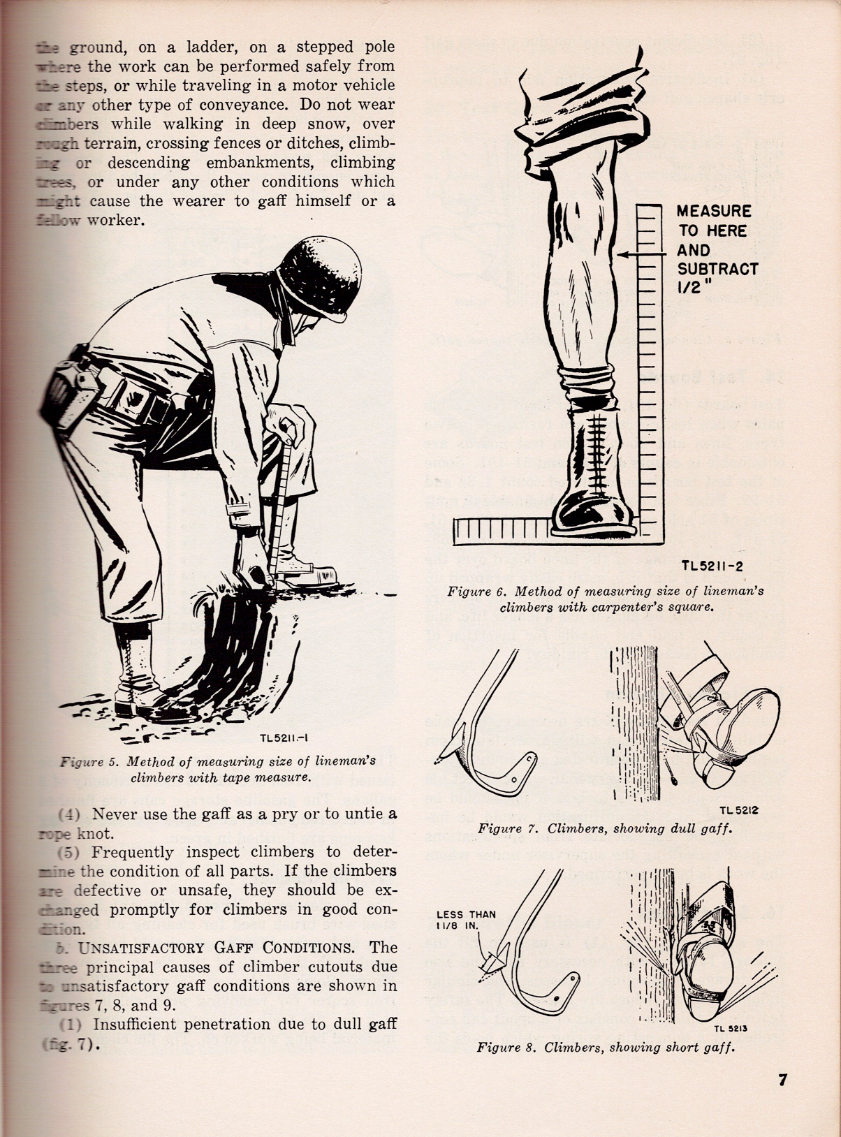
According to the May 1947 TM 11-372 field manual, they are measured from the bottom of the stirrup to the upper end of the leg iron. To determine the correct size of climber to fit the wearer, measure the distance from the bottom of the projecting knee bone to the underside of the shoe at the arch, as shown in the figures below, and subtract .5 inches.
Don’t wear the climbers unless needed, and be sure the gaff (the pointy part of the LC-5 climbers) is maintained well to dig into the wooden pole.
Prior to LC-5, there were two other LC climbers: an LC-6, which was 16″, and the LC-7, which was 17″. When LC-5 came out, it superseded both of these climbers as it came out in various sizes, thus negating the need for a specific size-based model.
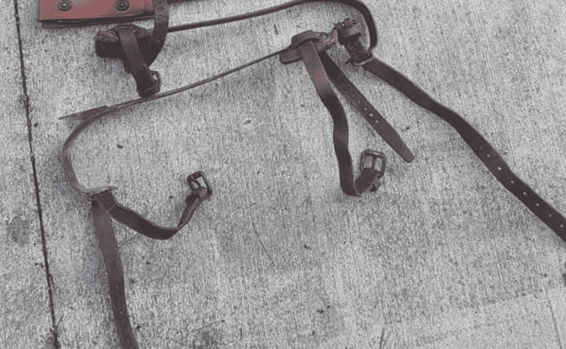
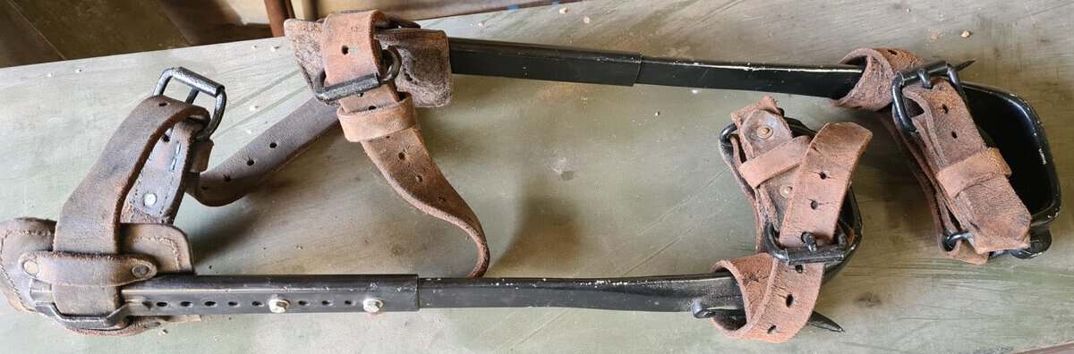
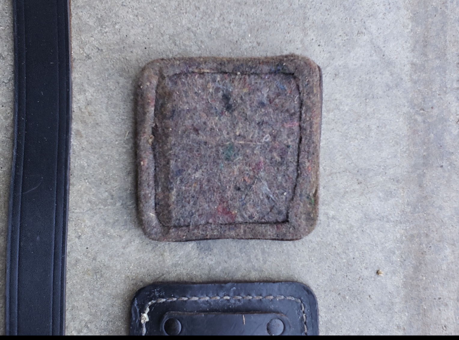
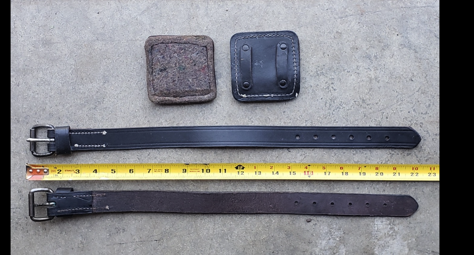
Note that the straps around the LC-5 climbers are made of leather and go through a square pad, which secures them to the upper calf and prevents chaffing. One side of the pad is leather, and the other side is the kind of cloth used to insulate the interior of canteen covers. This cloth is SAE F3, which is still in use today.
Lineman’s Climbers LC-5
Below are some images showing the straps
LC-5 Climber Calf StrapLC-5 Climber Calf Strap showing Buckingham labelPulled from WW2 Signal Group on FacebookPulled from WW2 Signal Group on Facebook
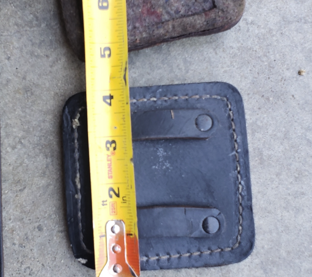
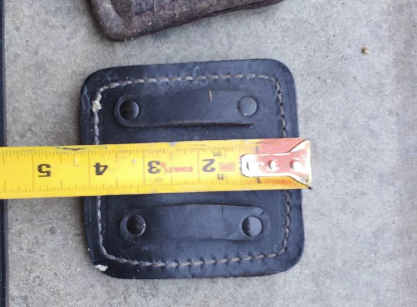
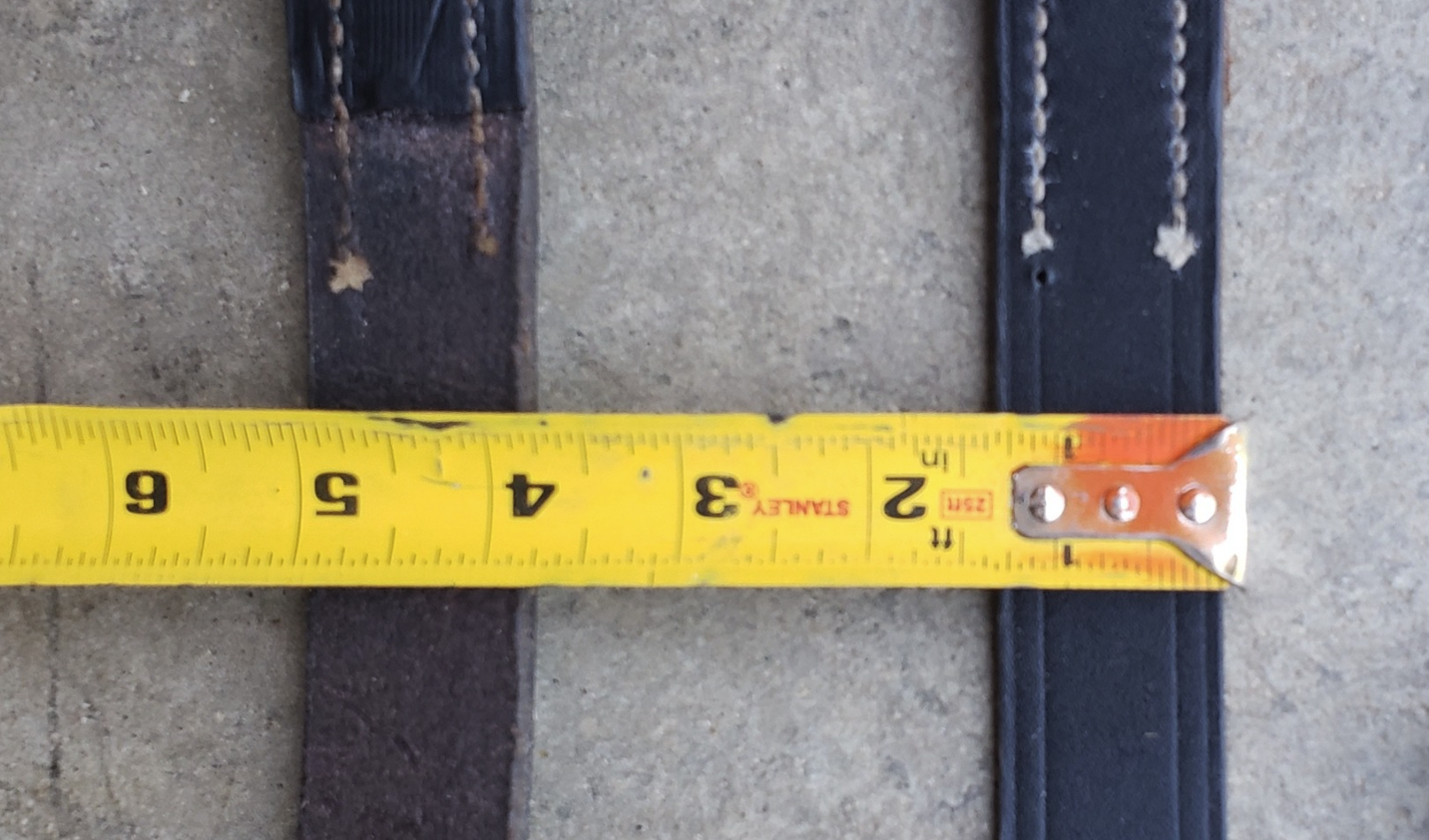
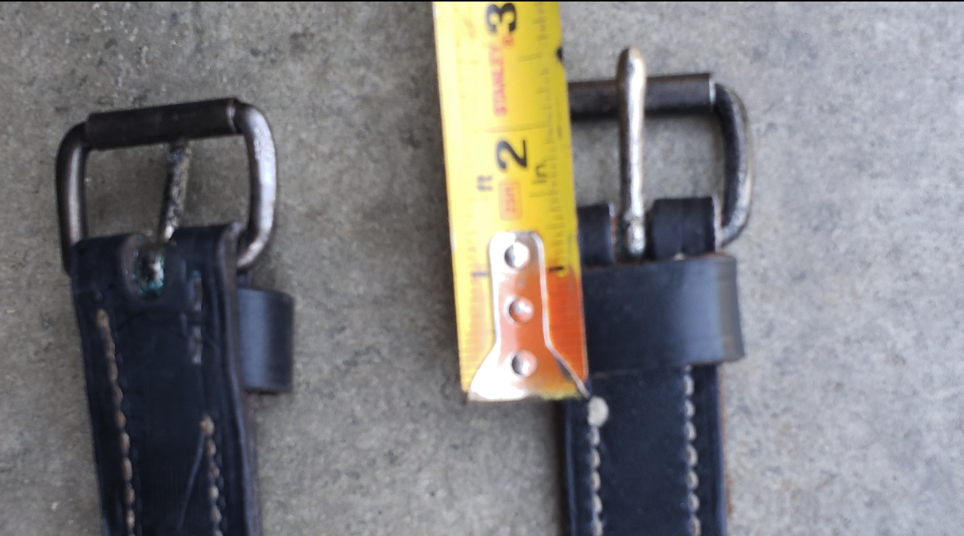
The images below show the measurements of the leg strap, leg strap loop, and calf pad. Images are taken from a New Old Stock (NOS) unit. The calf pad is about 4inches in width and length. The calf pad loops on the back are about .5 inches long. The calf leg strap is about 1.25inches wide. The calf strap loop is about an inch wide. The calf leg strap is about 22inches long.
The document below shows how to measure your leg and calf to be fitted for the pole climber size.
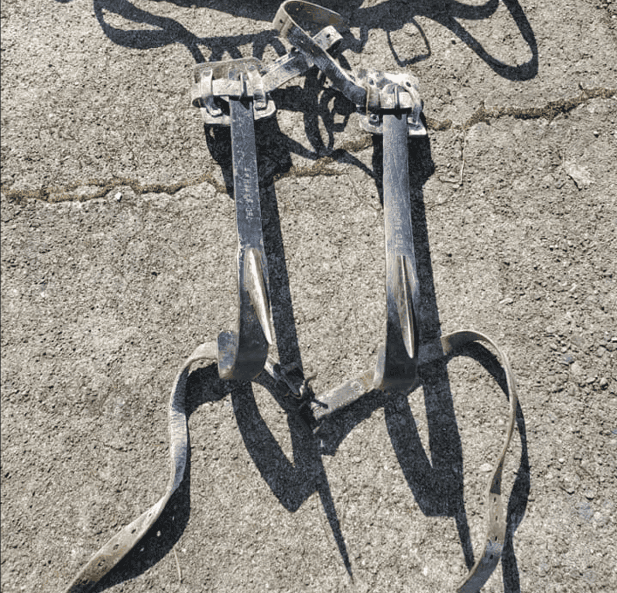
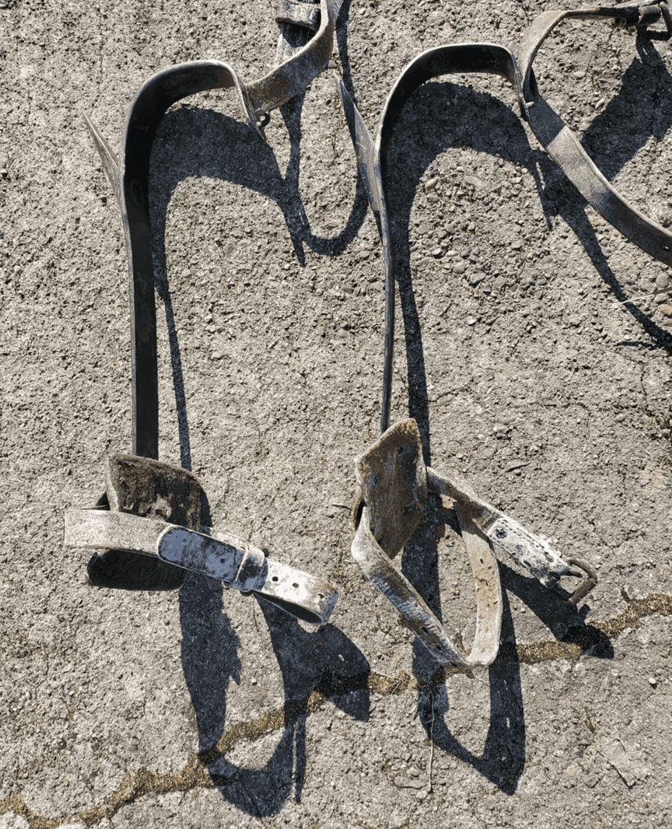
One thing to keep in mind when looking at the LC-5 Climbers is that there are two types. One for pole climbing and one for tree climbing. Each crew had a set of tree climbers, which appear to be just some kind of commercial tree spikes. These tree spikes appear to have no designated catalog number. You can tell they are tree spikes because the gaff is much longer for digging into the meat of the tree.
Pulled from the WW2 Signal Corps Facebook GroupPulled from the WW2 Signal Corps Facebook GroupPulled from the WW2 Signal Corps Facebook Group
SAFETY: Do not use original LC-23 belts or LC-5 leather straps and calf pads for climbing more than a few feet off the ground. It’s fine to wear to show the public or provide a demonstration where you climb up a wooden pole a few feet off the ground. However, you should not rely on almost 100-year-old equipment to support your weight more than a yard up. For the LC-5 straps and calf pads, you can buy modern versions and use those (or as close as you can get). For the LC-23 belt, nobody that I am aware of reproduces them. So you need to convert a modern one, as best as you can, to a WW2 version, or contract with someone to reproduce them.
LC-24 Twisting Plier,also called a Clamp: Used to crimp, twist, and splice wire.
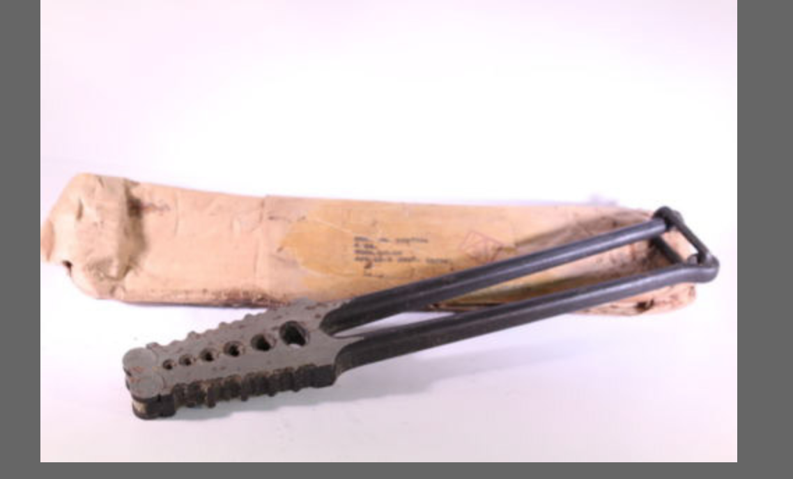
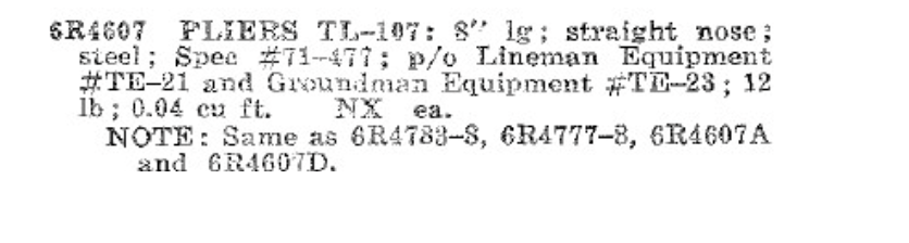
TL-107 Pliers, 8″: 8in in length, straight nose, steel. The US government contracted with various firms like Utica to make them. Indeed, Utica made a set of commercial pliers that are the same, called Utica 1950-8. 1950 being Utica’s catalog number and 8 meaning the pliers are 8 inches long. For a history of these pliers, see Alloy Artificats Utica Tools, Linemans.
This differs from the TL-13 and TL-13-A pliers, which were 6inches in length.
Sig5, Class 6, 6R
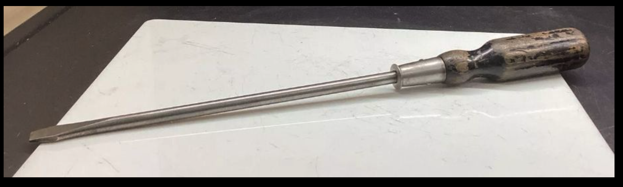
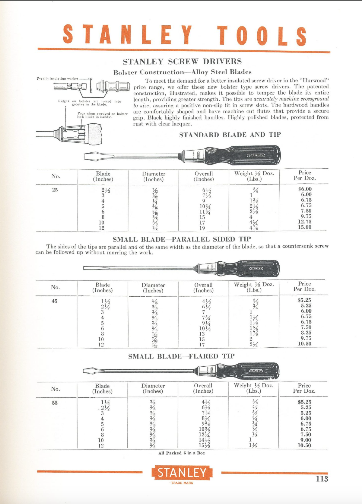
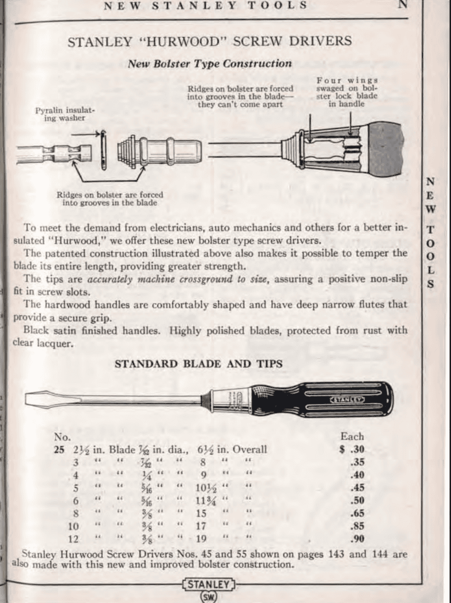
TL-106 Screwdriver: The screwdriver is similar to the Stanley 1934 # 25 driver. It had a 10-inch blade with a 3/8ths tip and 17in overall length. In 1934, it cost .85 cents.
Note that some screwdrivers might say “Forval” on the handle. This appears to be a French-made screwdriver. It’s unclear if this is a post-WW2 production or if the US Govt contracted with French companies after D-Day to produce these, which would make them “wartime dated”.
Now the specs say “or equal,” and there were other tool companies, such as Irwin, making tools during World War II. The IRWIN 800 seems like it would be a close equivalent. It is 14inches overall, the blade is 10 inches, and the blade tip seems to be close to 3/8ths (though depending on how you eye it, it might be 1/4th)
Additional images of the TL-106 Screwdriver can be found on Worthpoint here and here.
Sig5, Class 6, 6R
Screwdriver image pulled from ebay sale1939 Stanley Catalogue #25 ScrewdriverScrewdriver image pulled from a Facebook post in the WW2 Signal Corps Group Page#25 Stanley Screwdriver comes from the Stanley Tools 1934 Catalogue.
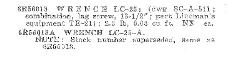
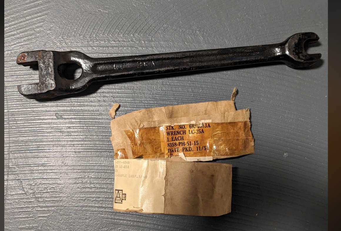
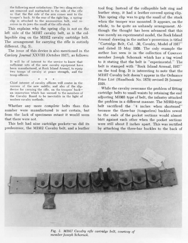
LC-25-A Lineman Wrench: The LC-25-A Wrench was used to secure cross beams to telephone poles. It differs from the LC-25 wrench. See the “load out” images towards the bottom for the differences in appearance.
Sig5, Class 6, 6R
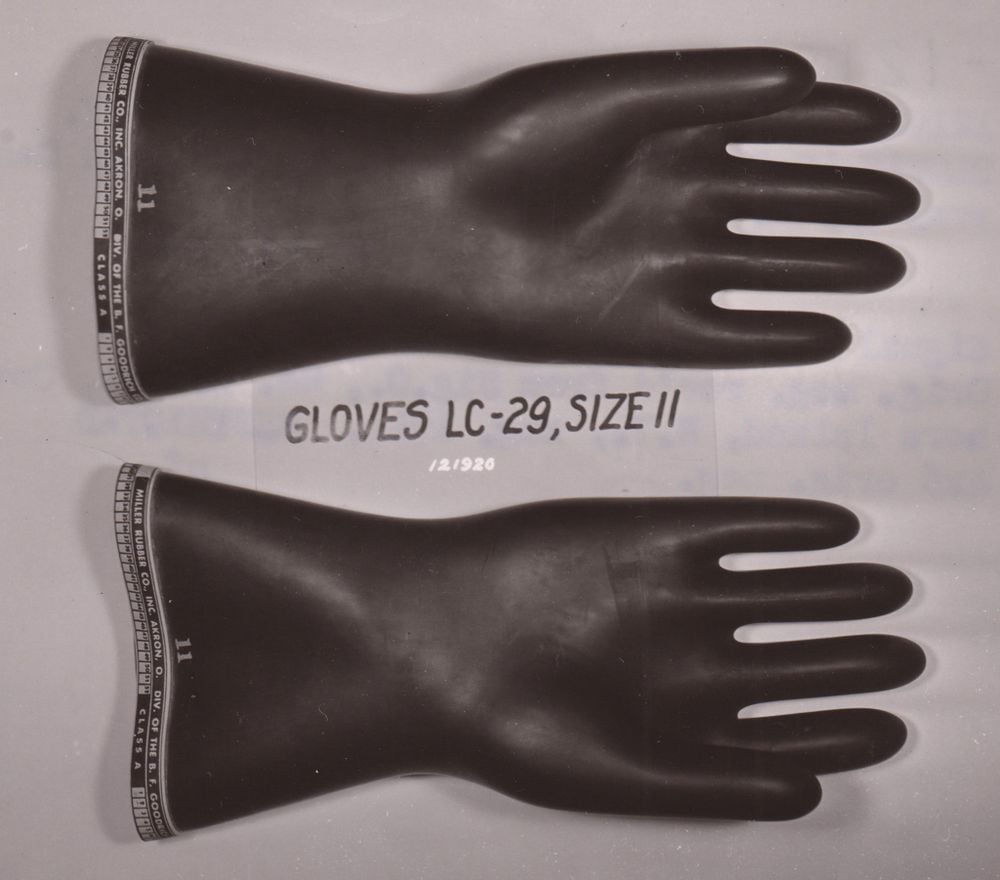
LC-29 Gloves, Rubber: This was not part of TE-21 but something they likely kept on hand. Black in color. Likely worn over the leather gloves for working with exposed lines, as rubber is an electrical insulator. It came in three different sizes, I believe.
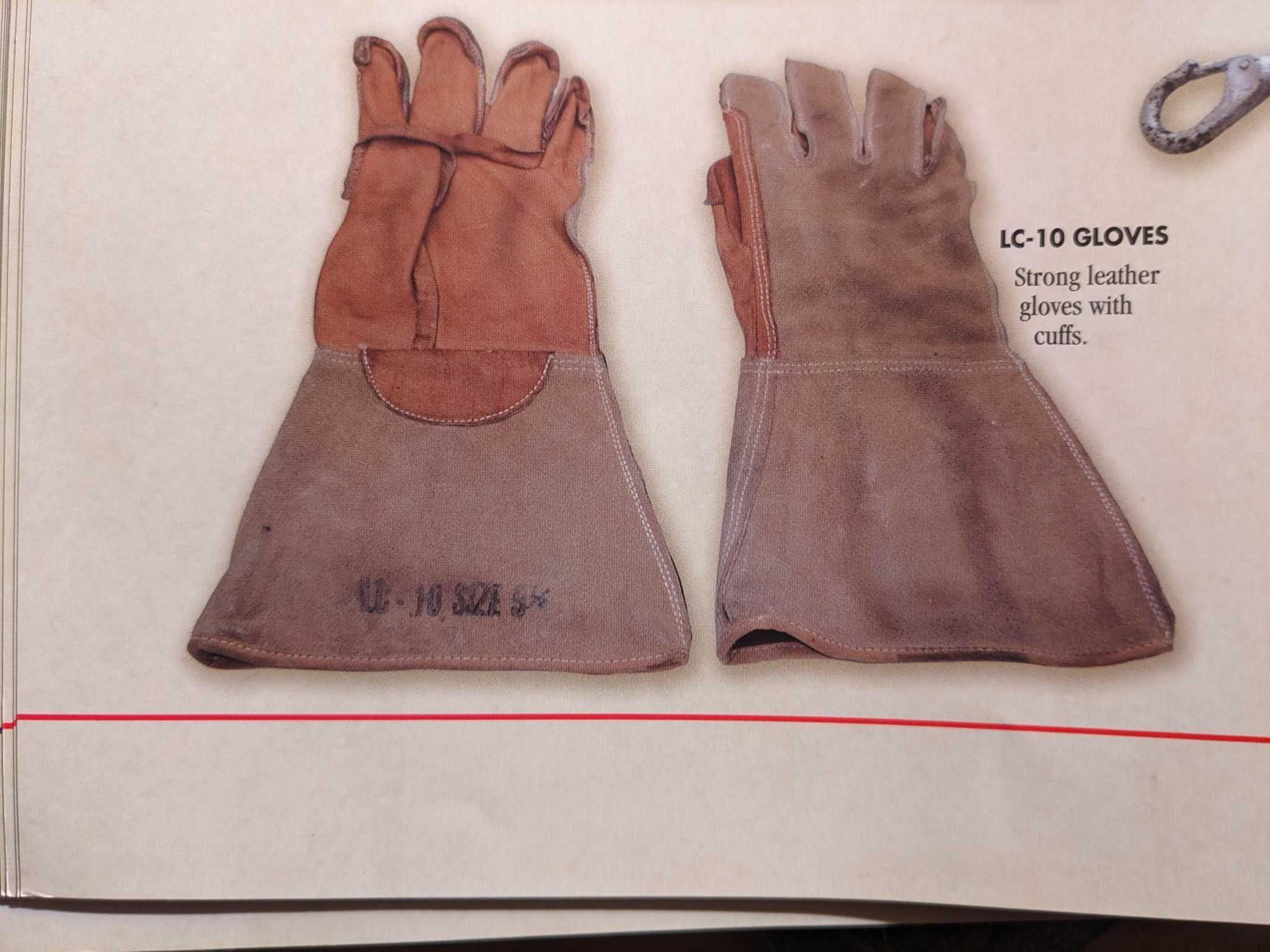
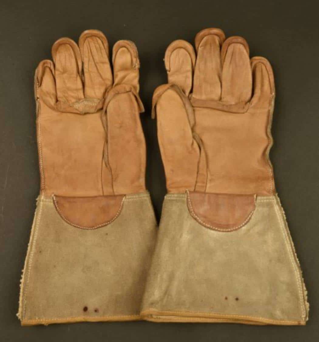
LC-10 Gloves, Leather: These gloves were leather and had cuffs. They came in multiple sizes. Note that AI is saying there’s an LC-29 leather glove. That’s wrong because it scraped the wrong information. Such a glove doesn’t exist!
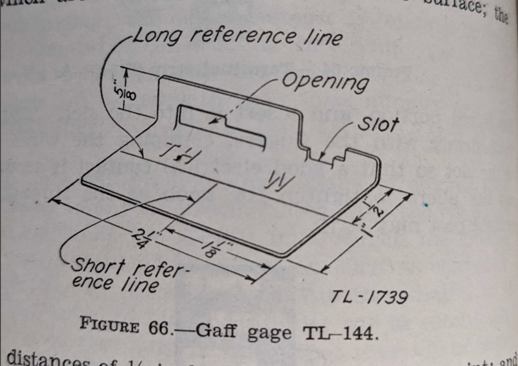
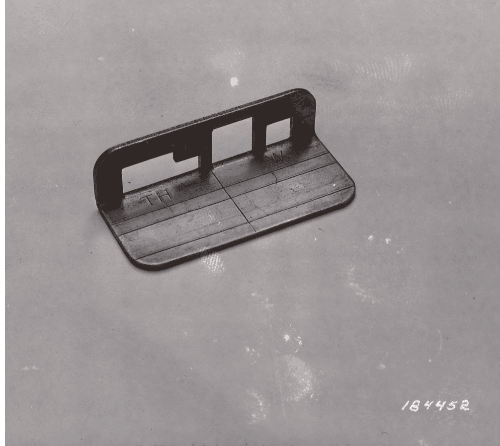
TL-144 Gaff Gauge or Gage: Used to measure the spikes on the climbers. This was not part of TE-21 but something they likely kept on hand. It may have come in a few different designs, as shown below. However, neither design shows any kind of cut in the base/short reference line area.
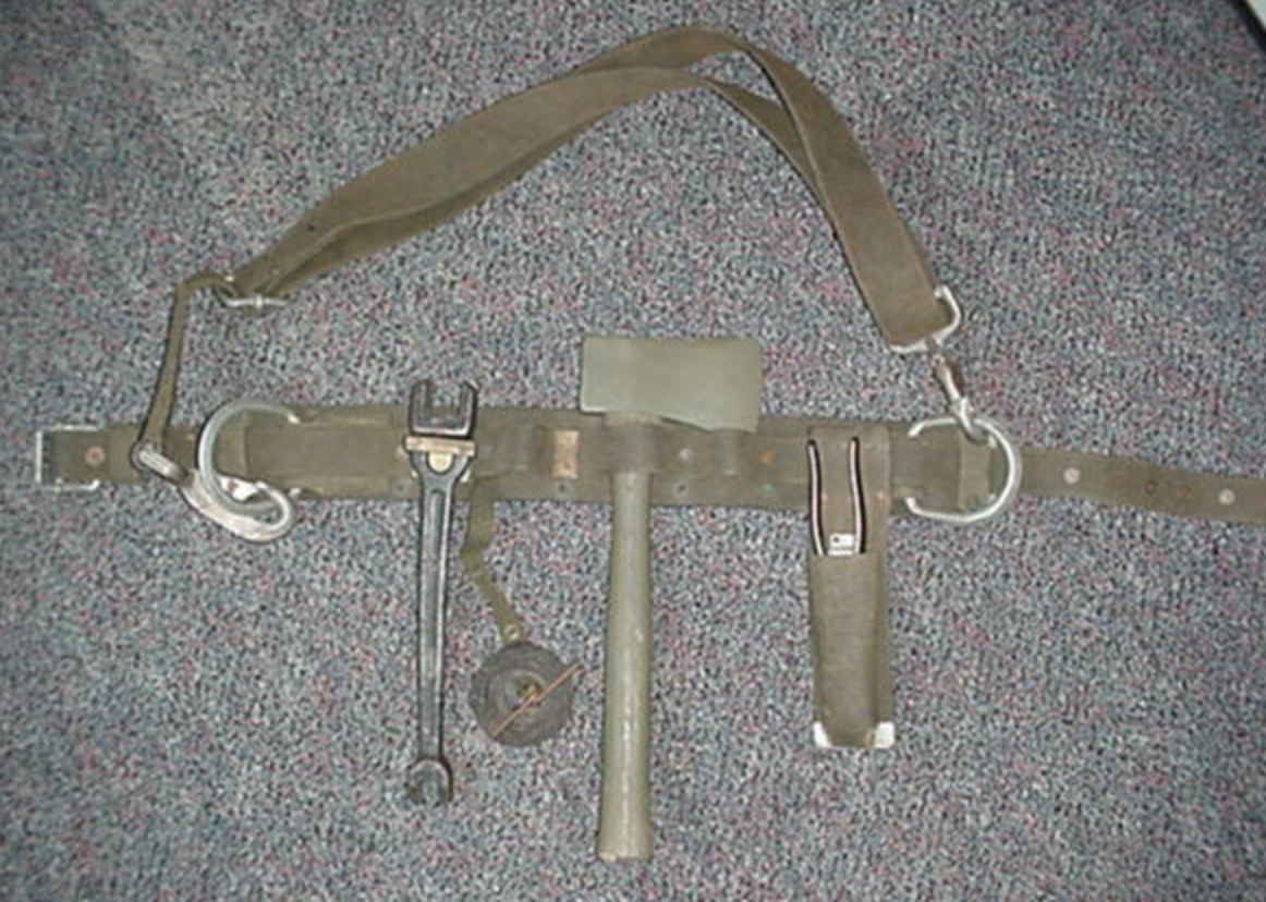
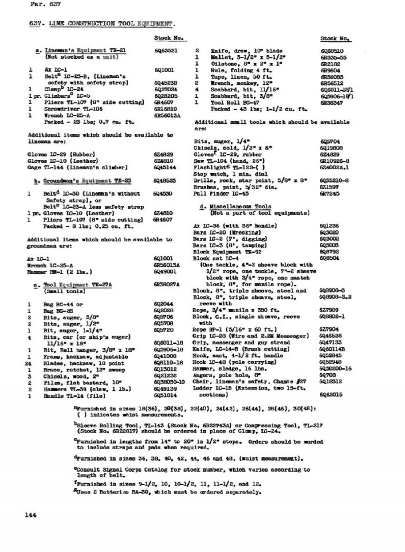
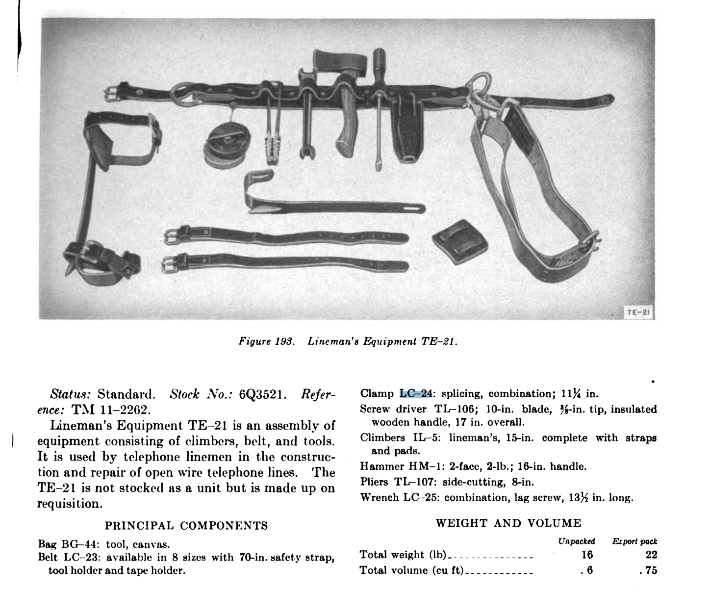
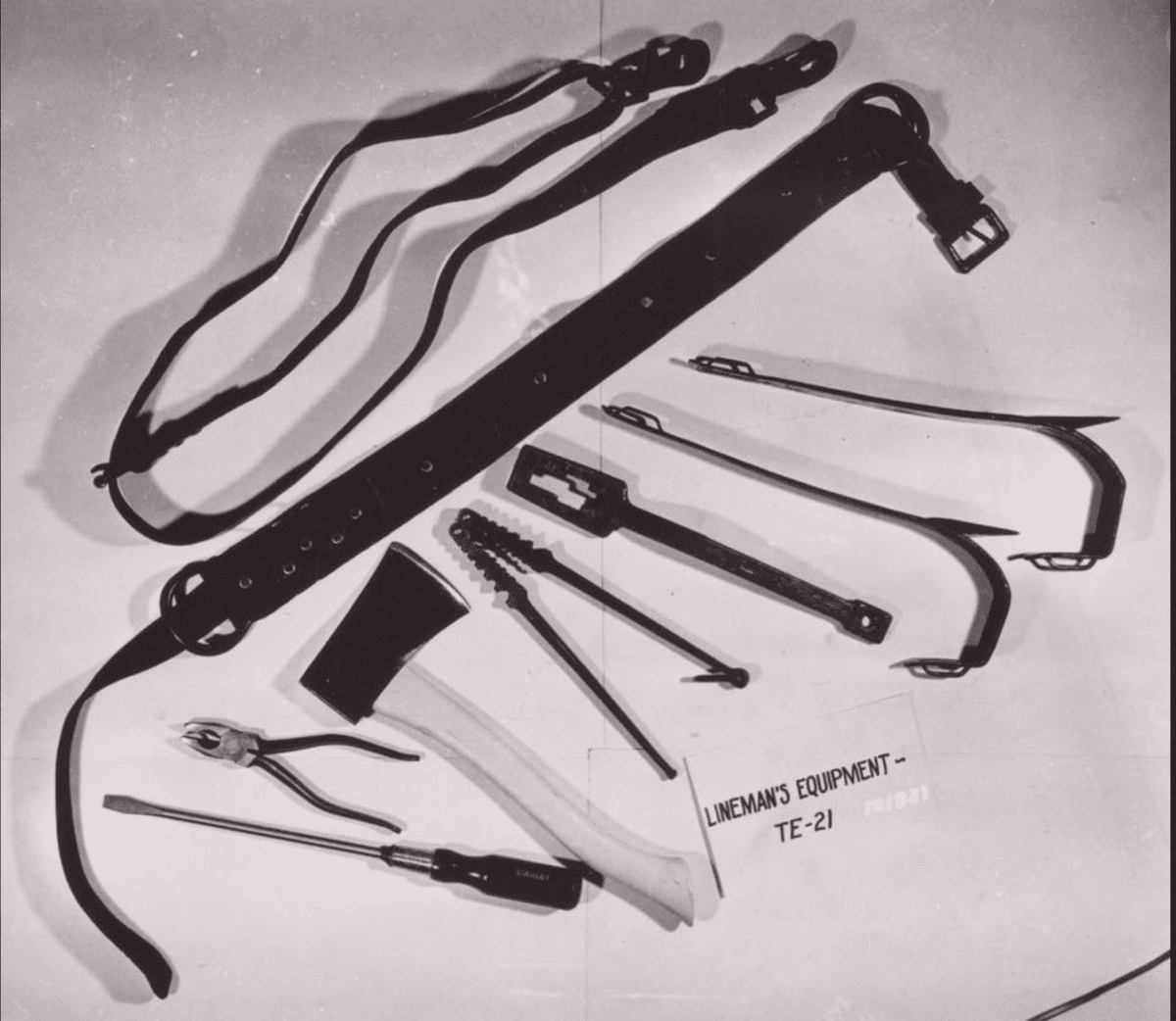
Lineman’s equipment TE-21: TE-21 is the designation for all the equipment put together. When laid out, it looked like this. I suspect some of this stuff was traded off between the guy on the pole and the guy on the ground. Also, the image might be a post-war one, as the Hammer, HM-1, isn’t listed. Instead, a TL-39 Hammer is listed.
From TM 11-487 Oct 1944, pg 144. Shows the equipment for TE 21, TE 23, and TE 27a. I suspect that many of the tools were interchangeable on the job site.
Post War Lineman’s Equipment TE-21 March 1951 via TM 11-487B; A display load out type image
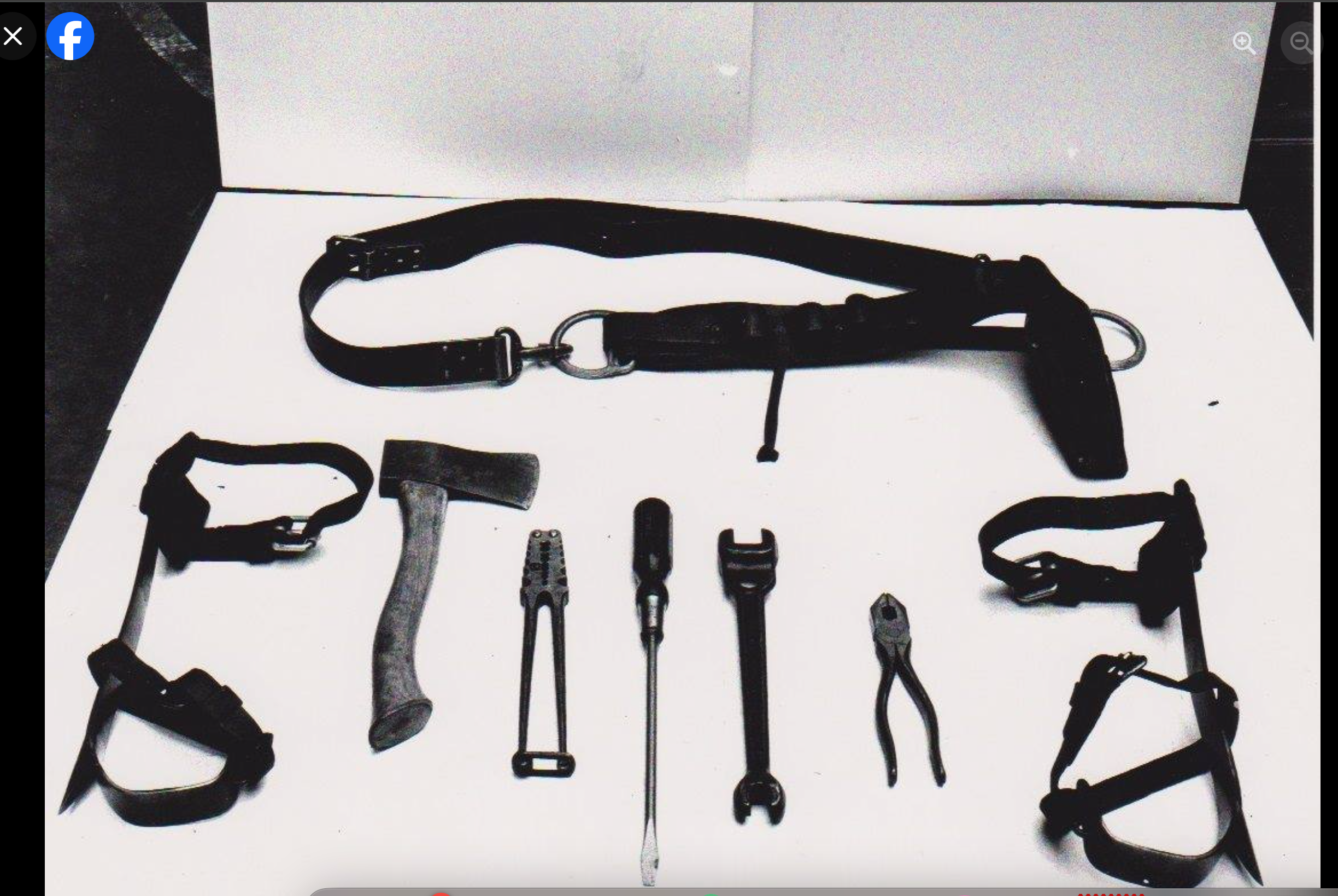
A display “load-out” type image. This is probably a later image because the LC-25-A Lineman Wrench appears
Lineman’s Equipment TE-21 “load out” type image. This is an earlier one because it shows the LC-25 Lineman Wrench.
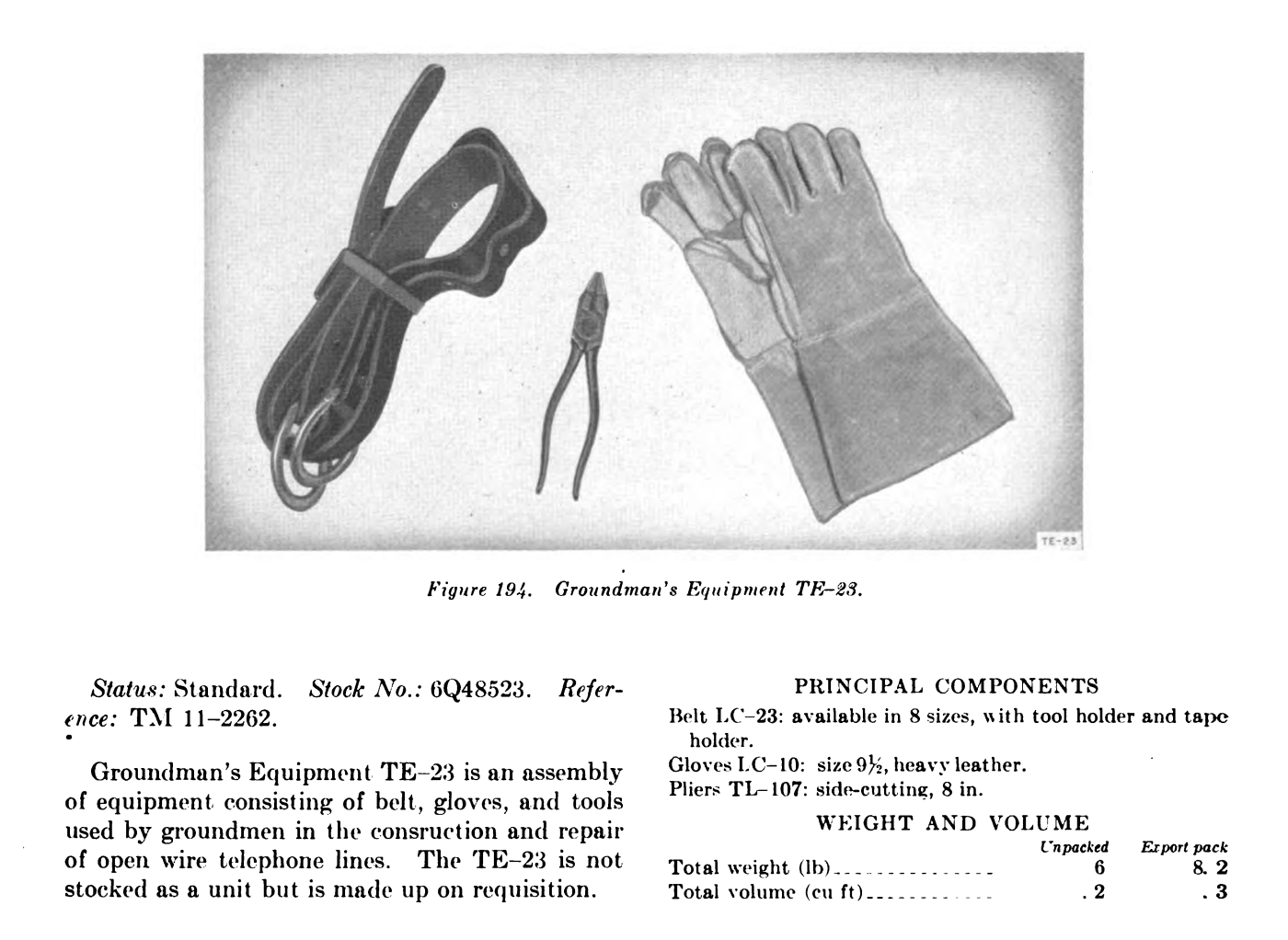
Groundman’s Equipment:
LC-23 belt w/o strap [late ’44 date]: Same as the equipment for the lineman.
LC-10 Gloves, Leather: Same as the equipment for the lineman.
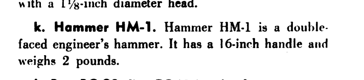
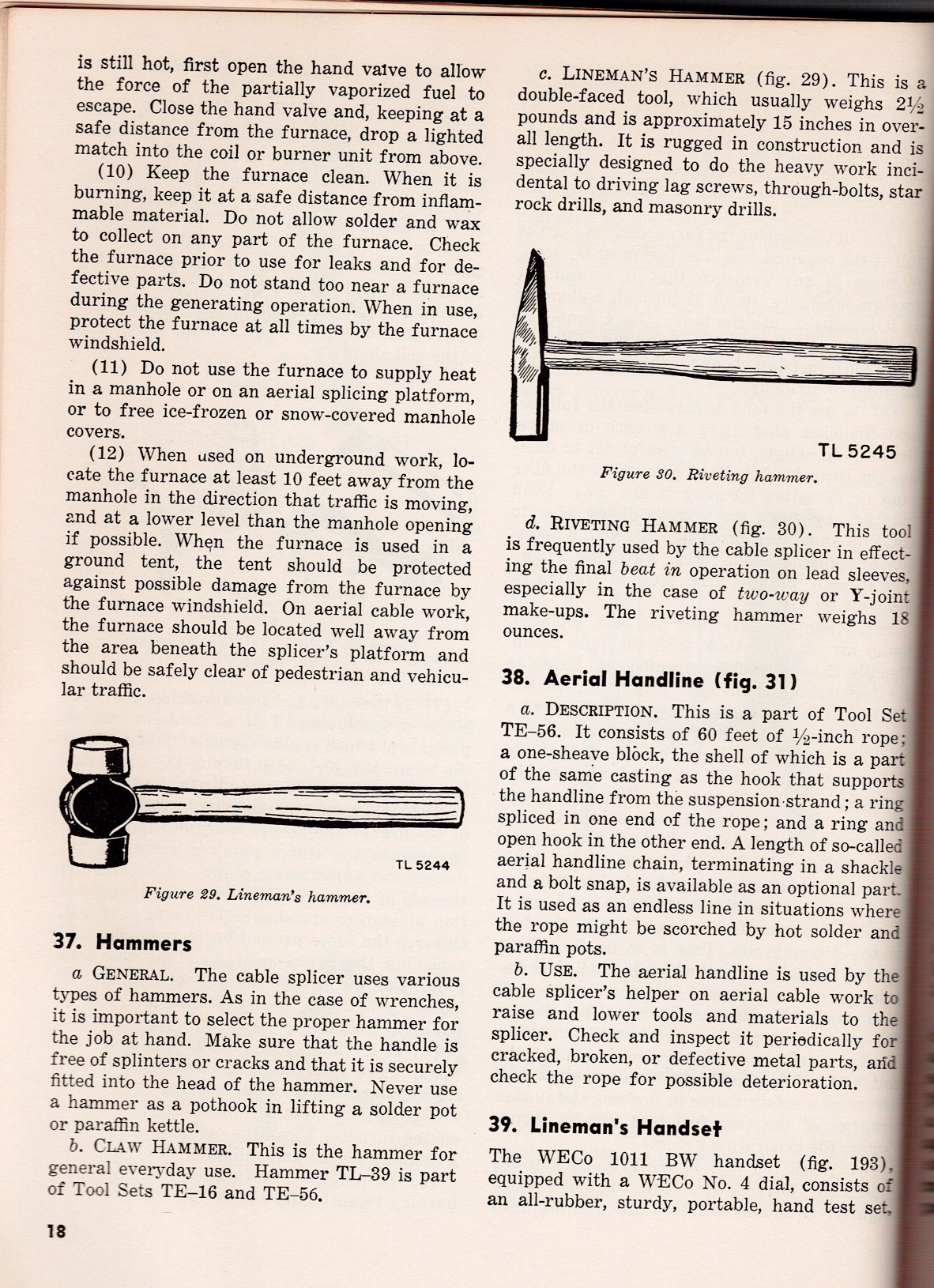
HM-1 Hammer, 2lb: This is a double-faced engineer’s hammer with a 16-inch handle and a weight of 2 pounds.
Now, according to the May 1947 TM 11-372 field manual, the HM-1 hammer is also called a Lineman’s Hammer and is 2.5 lbs and 15 inches in overall length. I guess that some “bean counter” must have mis-measured it.. There’s also a TL-39 Hammer, which is the Claw Hammer.
Note that in this manual, the images all start with “TL”; this isn’t meant to be interpreted as a “TL” or “tool” designation for the item depicted but rather a way of numbering images specific to this manual.
Groundman’s Equipment TE-23: TE-23 is the designation for all the equipment put together. When laid out, it looked like the following:
Groundman’s Equipment TE-23 March 1951 via TM 11-487B
Other items:
TE-33 tool kit – This kit consisted of a leather case, CS-34. Inside the case went a pocketknife, TL-29, and a small set of 6in pliers called TL-13 or TL-13-A.
Now the TL-13 plier types are a military designation of what is essentially the same set of commercial pliers called Utica 1950-6. 1950 was just the catalog number and not the year, and 6 refers to the pliers being 6 inches. Indeed, some 1950-6 pliers are also stamped TL-13, suggesting that the US military contractors acquired pliers “off the shelf” and just stamped them with their designation. For a history of these pliers, see Alloy Artificats Utica Tools, Linemans.
One thing to know about these pliers is that the US Army Training Videos regarding splicing is that the wire in use, like W-110B on various reels, may have a rubber insulation on the outside.
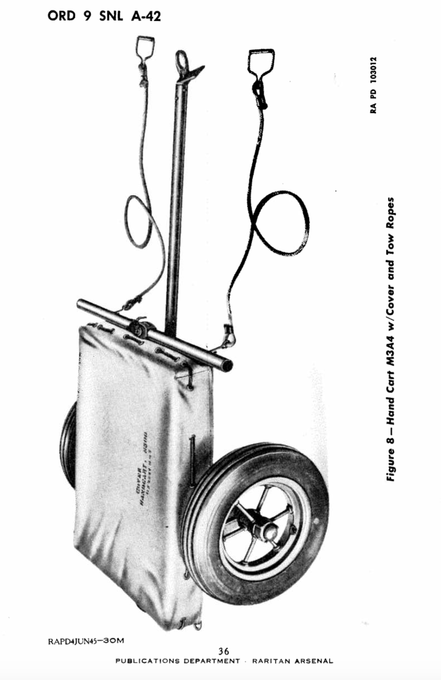
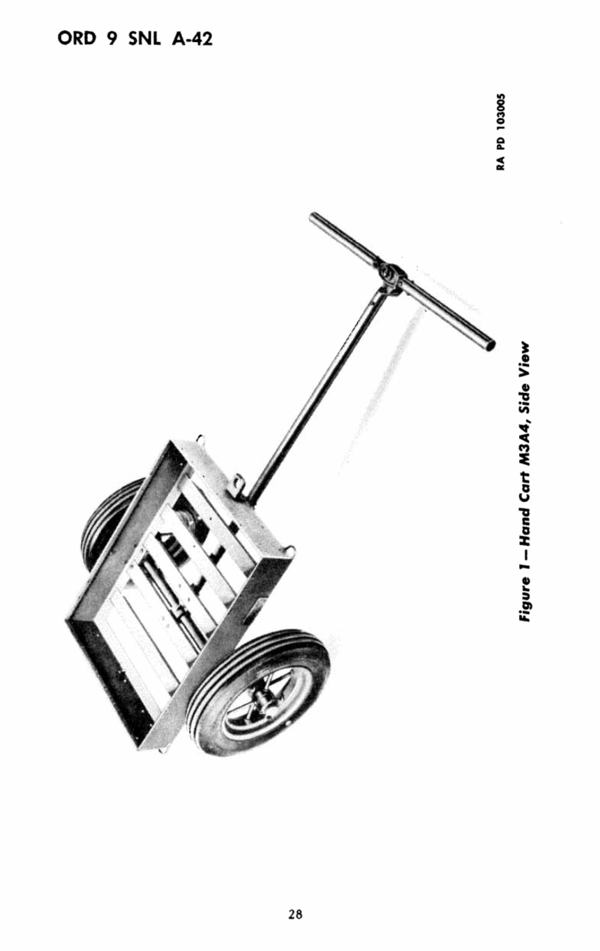
2 DR-4 reels [no -A suffix]: The drum consists of half a mile of W-110-B wire. May have W-110B wire (as indicated in this 1941 Signal Corps Splicing video), which consists of 3 strands of copper and 4 strands of steel. Covered by a rubber compound. Then a braid is wrapped around the rubber to help protect against crushing. You likely won’t find the original wire.
W-130 Wire – used by infantry for short, temporary lines, such as to an observation post. The wire has 6 steel strands and 1 copper. Covered by a thin rubber insulation. You likely won’t find the original wire.
W-150 Wire – Same specs as W-130, except the rubber is wrapped with a braid. You likely won’t find originals.
WD-1/TT and WD-1A/TT (both abbreviated as WD-1) – These are post-war wires and consist of four tinned-copper strands and three galvanized-steel strands, and an insulation of polyethylene with an outer nylon insulation jacket. Now, the wire on the market today is mainly this stuff, and as such, World War Two era signal corps splicing techniques may not work. So to shave the wire, you may need to use a modern tool.
2 DR-8 handheld reel rigs [no -A suffix]:
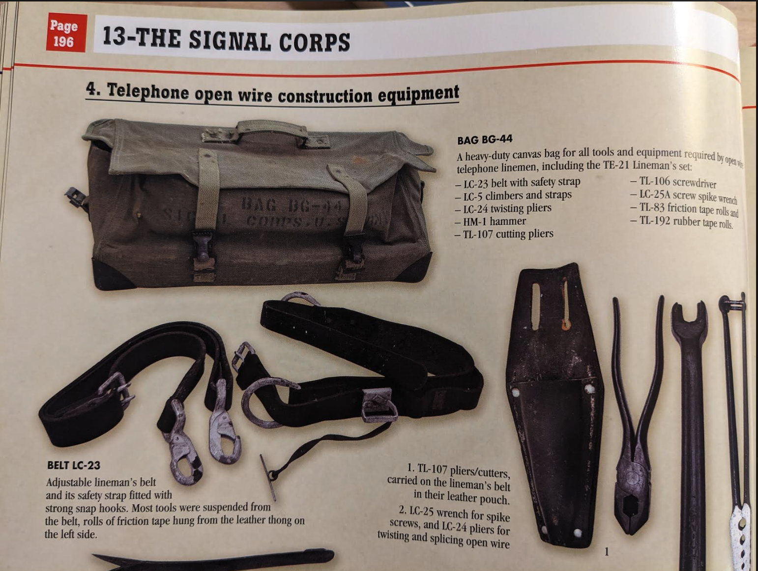
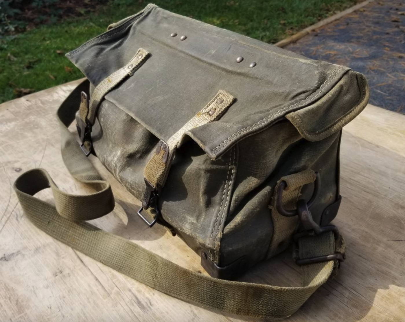
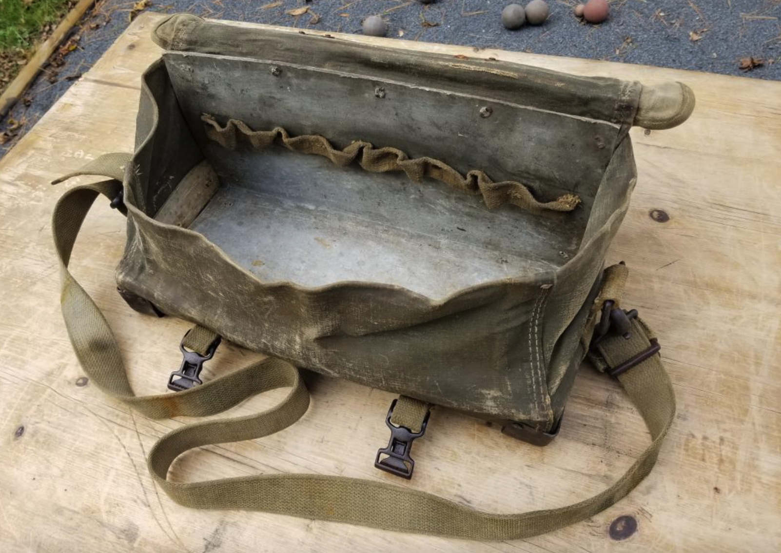
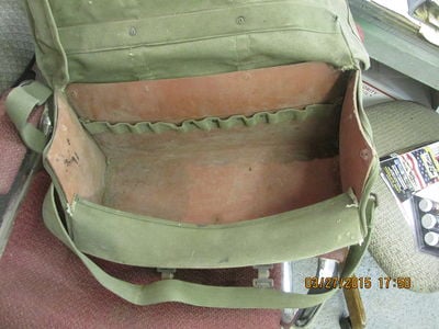
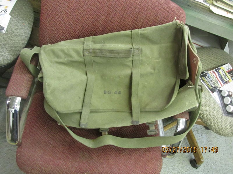
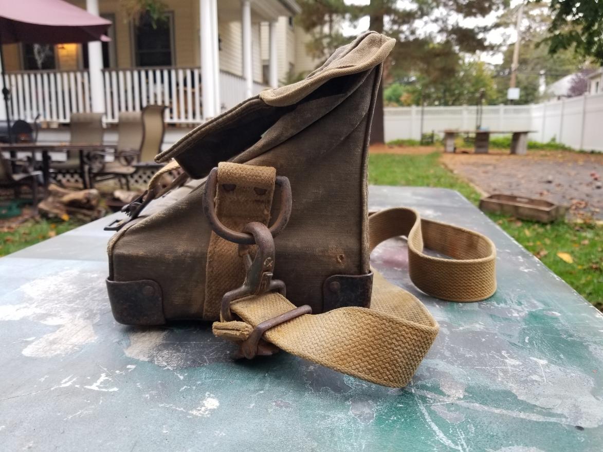
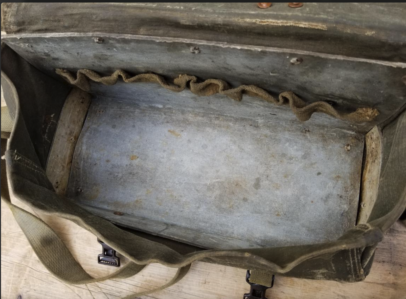
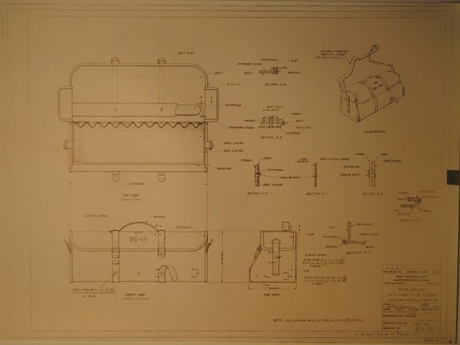
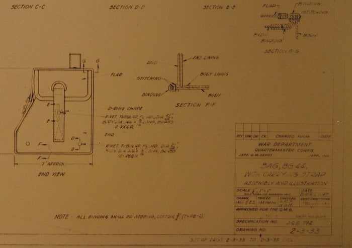
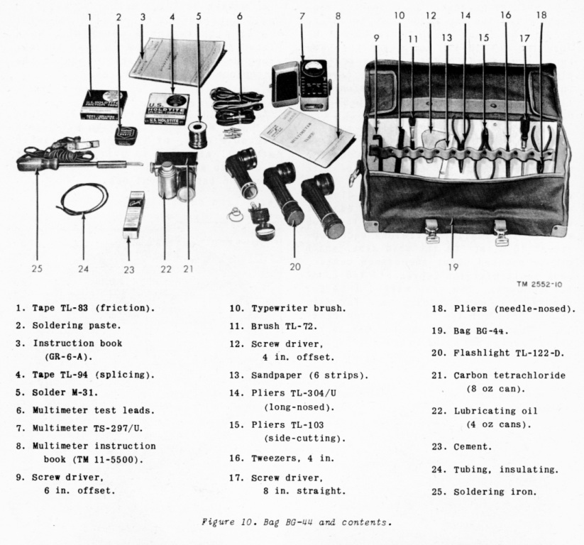
1 Bag, BG-44: This is the tool bag the team would put all their tools into for the job. You can see images of the bag at the US Militaria forum here.
Another set of BG-44 images, including the schematics/blueprints. Note that if there’s an anchor logo on the buckles, it’s Anchor Brand, a trademark (June 3, 1928) of North & Judd Manufacturing in New Britain, CT. Now a part of Buckles International.
Not all lineman jobs required the BG-44 bag, but it contained a few different tools.
This may be a post-war configuration
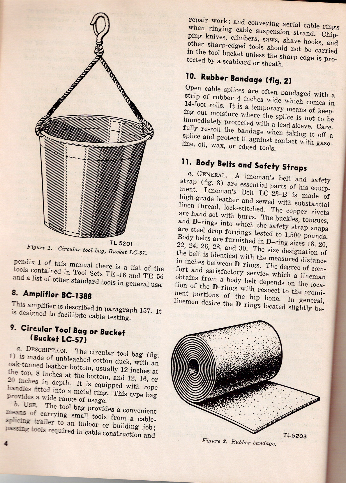
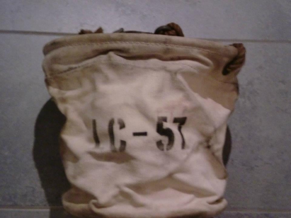
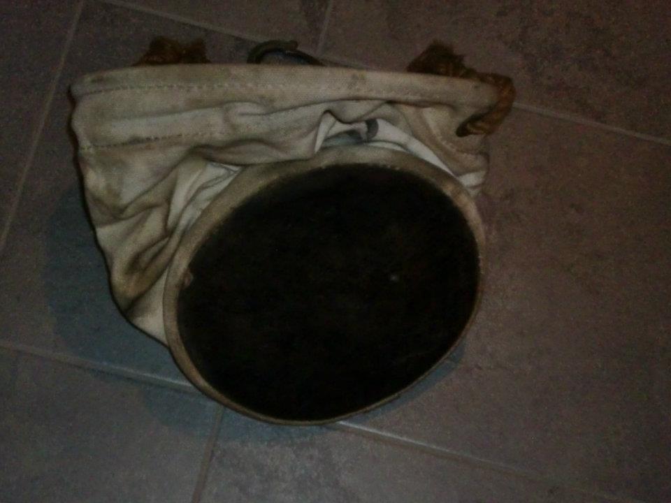
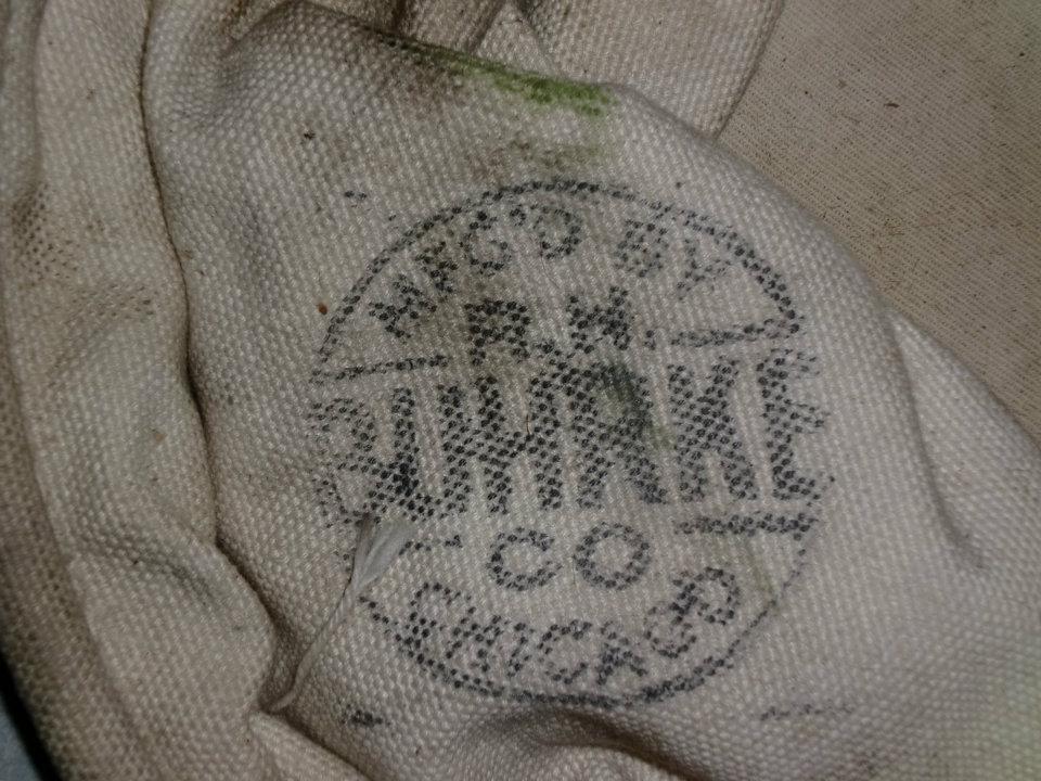
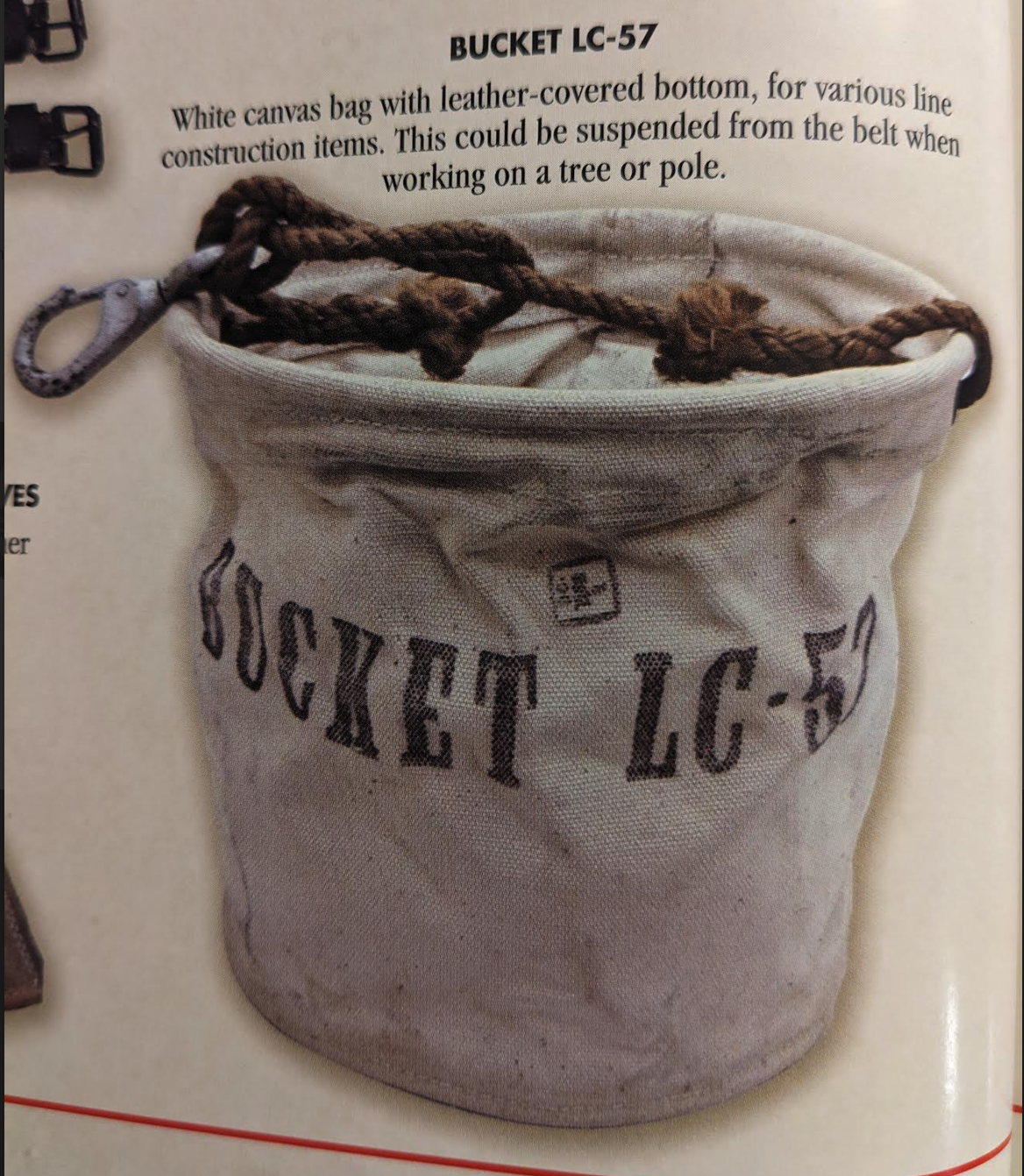
2 LC-57 Buckets, Canvas: A white canvas bucket for hauling tools around and up poles. It had what appears to be a metal ring sewn in around the top to provide support and reinforcement, and a leather bottom.
According to the TM 11-372 Telephone Cable Splicing Manual from May 1947, the LC-47 circular tool bag bucket is made of unbleached cotton duck cloth with an oak tanned leather bottom. 12 inches at the top, 8 inches at the bottom, and either 12, 16, or 20 inches in depth. It had rope handles fitted into a metal ring. Now, the fact that the bucket came in different depths presupposes that there are different model variants of the LC-57.
Describing materials and sizes of the LC-57 Bag Bucket
An example of a probable commercial LC-57 bucket
Paperwork and Forms
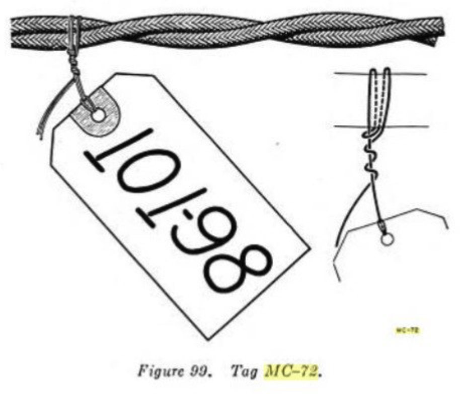
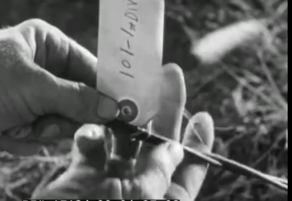
While not listed, some linemen marked the lines to identify what they are. They likely used a pencil or an ink pen to scribble what the line is. The identification tag may have been a standard ID tag. According to RadioNerds, there was an MC-72 tag that existed in 1927. It has a brass eyelet and a 12-inch tie wire for marking cables.
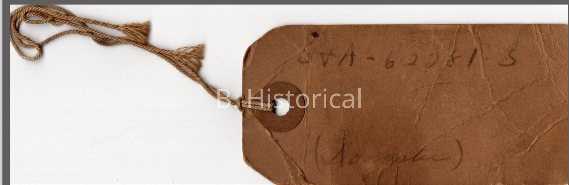
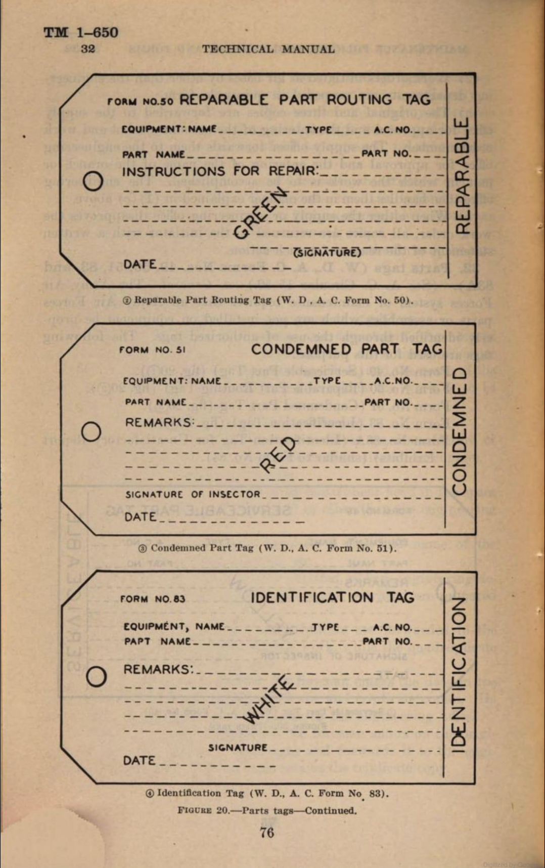
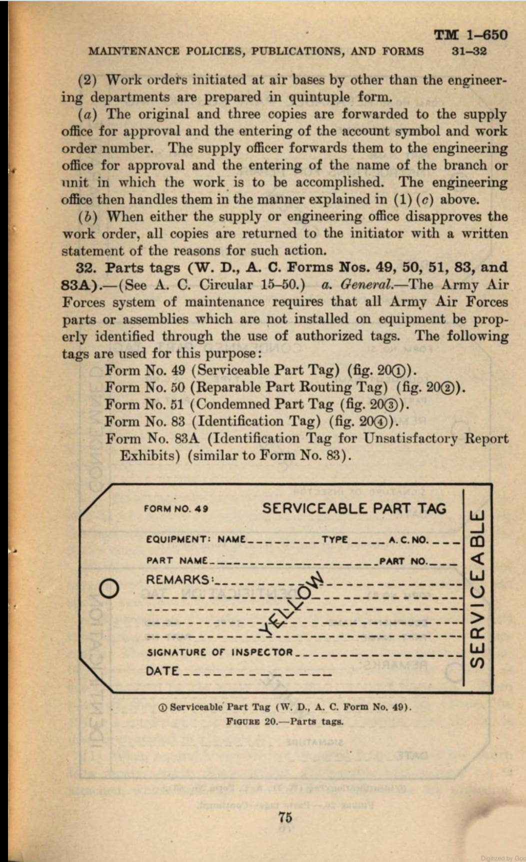
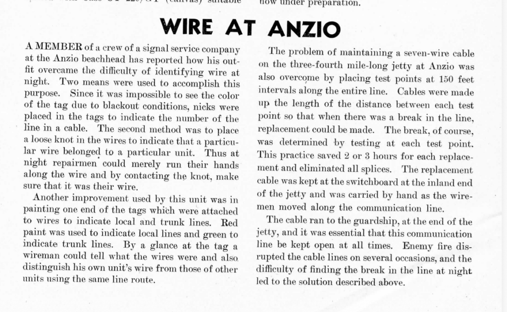
Lastly, in Signal Corps Technical Information Letter Jan 1945 No 38 on page 8, “Wire at Anzio,” it’s reported that they used colored tags to identify lines, but couldn’t see them in the dark, so they added notches to identify the number of the line in the cable. It was also mentioned that they painted them to identify local vs trunk lines with red for local and green for trunk.
If you wanted to be historically accurate, you could get some basic white ones from Amazon and use wire to attach them. According to the 1941 Signal Corps, Pole Construction video, soldiers used white tags with wire to identify lines. Then scribble on it any relevant notes and add a notch if needed to identify the line, and some paint to differentiate the type.
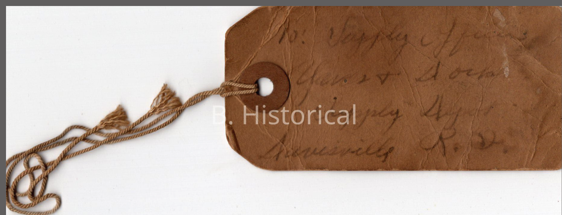
I’m unsure if the wire part of the tag was dropped for a string as the war continued, if the brass was dropped for a cardboard support, and/or if the color of the tag was switched to brown (as shown on that repair tag above) to better camouflage the lines.
The LC-A wrench looked different when compared to the A version.
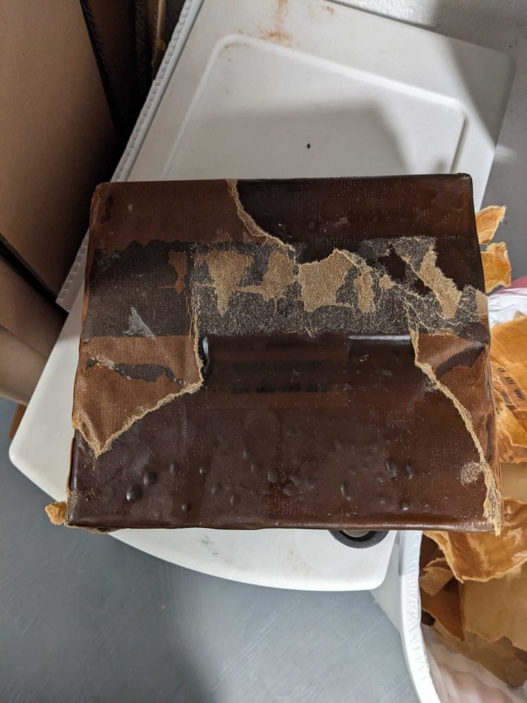
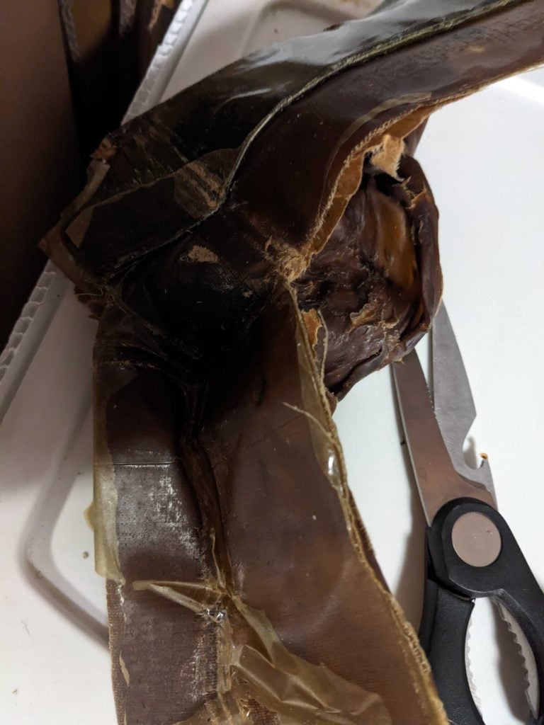
The LC-25-A Wrench was used to secure cross beams to telephone poles. I purchased mine off of eBay for 30 dollars in March 2025, shipped. It came in new, unopened condition. It was wrapped in two brown paperish wrappers with a paper tag attached to it.
The first tag was an inspection wrapper dated 3/1960. The second tag was the initial packing tag. It was dated 11/1951.
Now, to my knowledge, the wrench didn’t change between WW2 and the Korean War. I don’t have the wrappers, but the 11/1951 wrapper is 6in long and 2in wide. The 3/1960 is 7in long and 2in wide. You can download a PDF here if you want to try and recreate it.
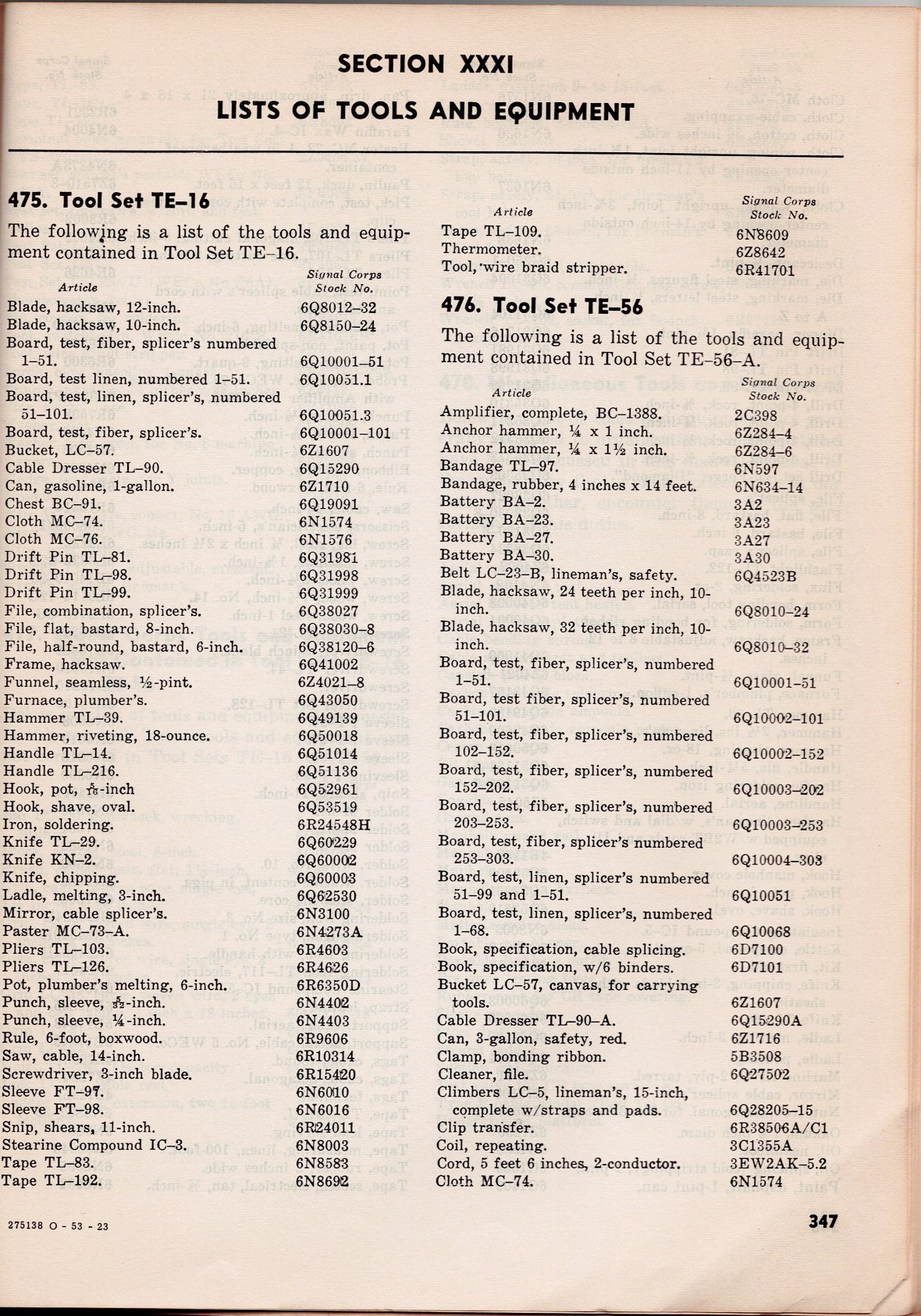
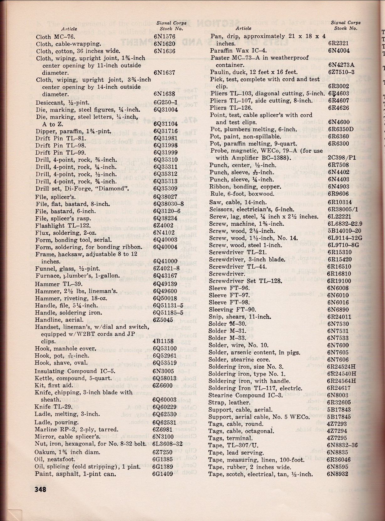
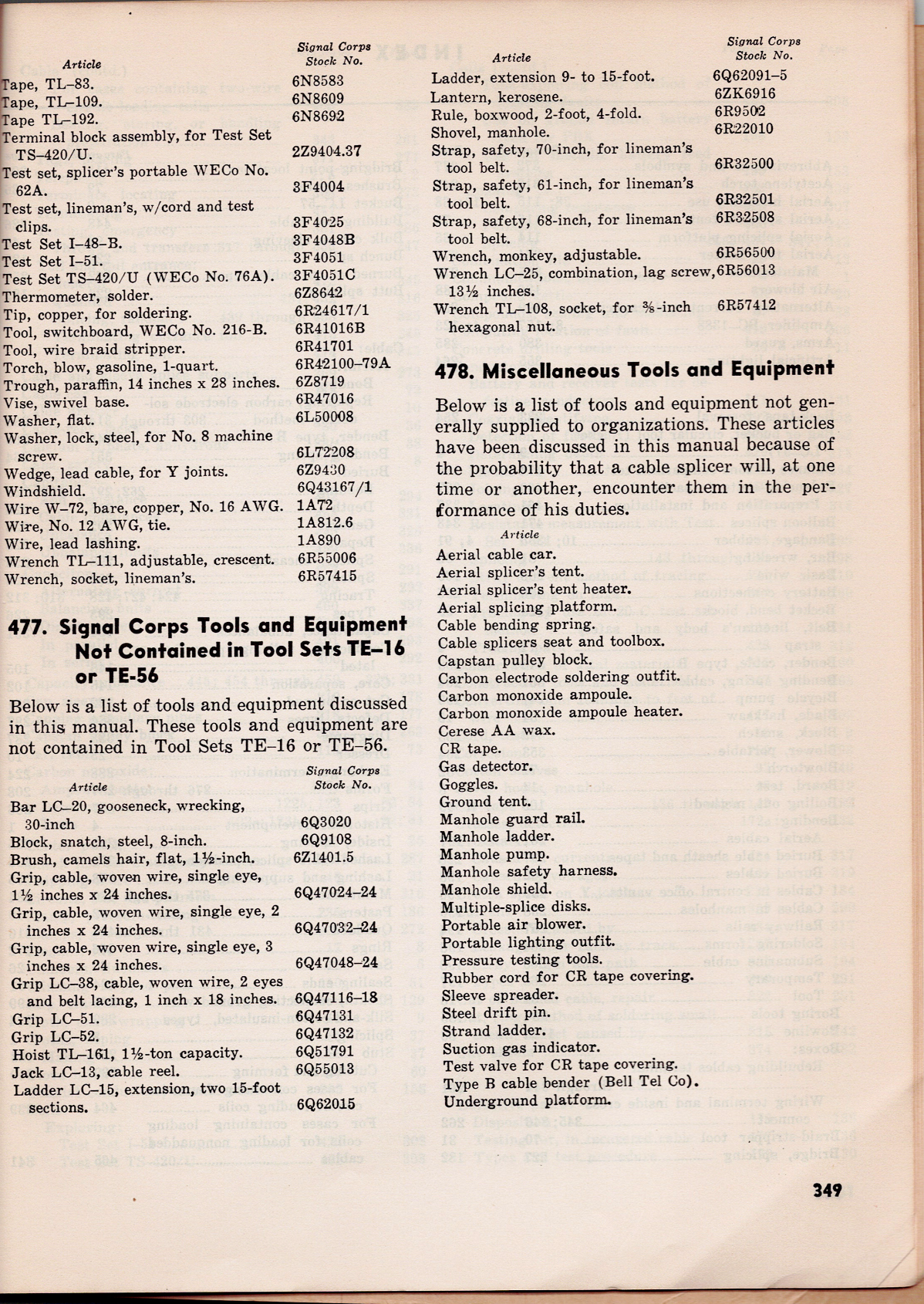
Tool Set TE-16 and Tool Set TE-56
Below is the list of tools and equipment contained in both sets. They come from the TM 11-372 Telephone Cable Splicing Manual from May 1947. While post World War II, it seems the equipment for the sets wouldn’t have varied by much, if at all.
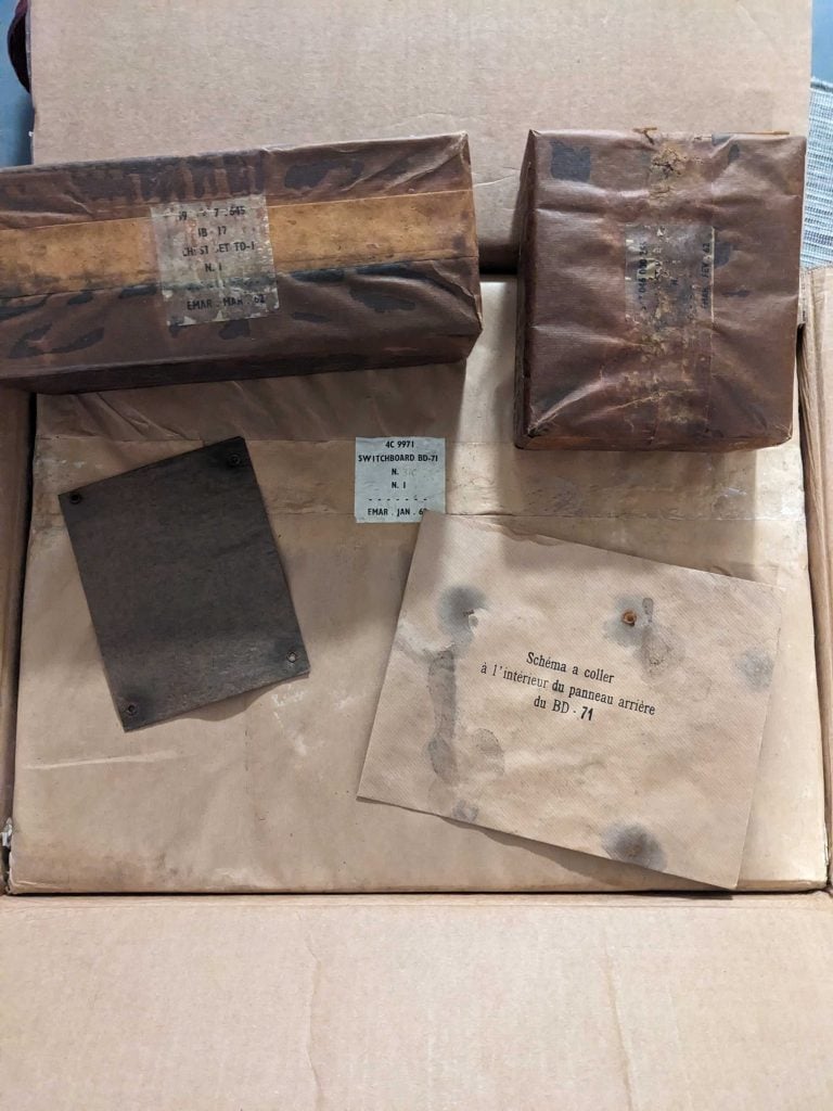
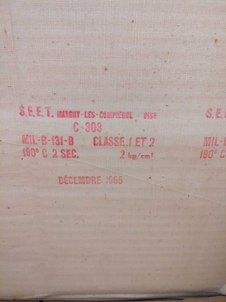
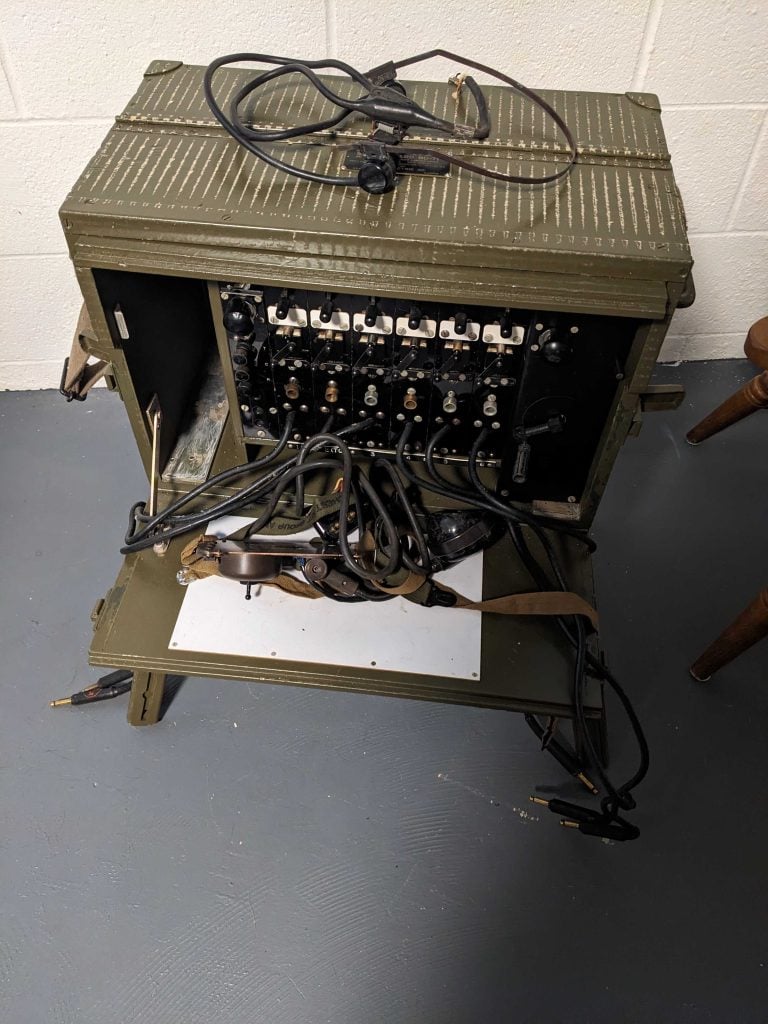
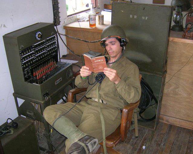
Advanced Guard Militaria offered a French repacked switchboard for $250 dollars, shipped. When I saw that I pounced on it as it was a good price and I wanted to rebuy the BD-71 switchboard I once had. I bought that one for $80 dollars at an auction in 2011.
The switchboard came in a large box and a smaller box contained the accessories.
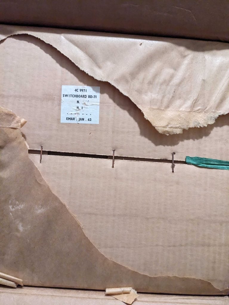
Unpacking the switchboard was like peeling back an onion. First I had to peel back some paper coverings and open the box.
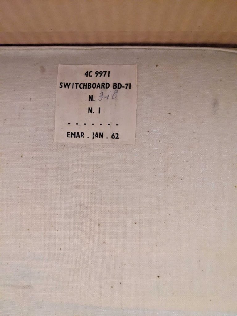
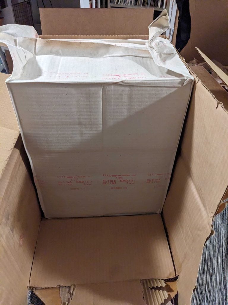
Next, I discovered some kind of canvas, metallic-backed waterproof bag. When I opened it up, I probably should have done it outside to be safe as the bag appeared to be vacuum sealed, and yet when I opened it, I heard gasses escaping.
Who knows what kind of gas might have been pumped into the bag prior to sealing? At any rate, I got a lung full of 1968 French air.
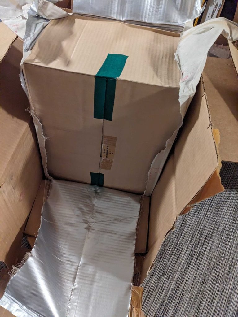
When I opened it up, there was another box!
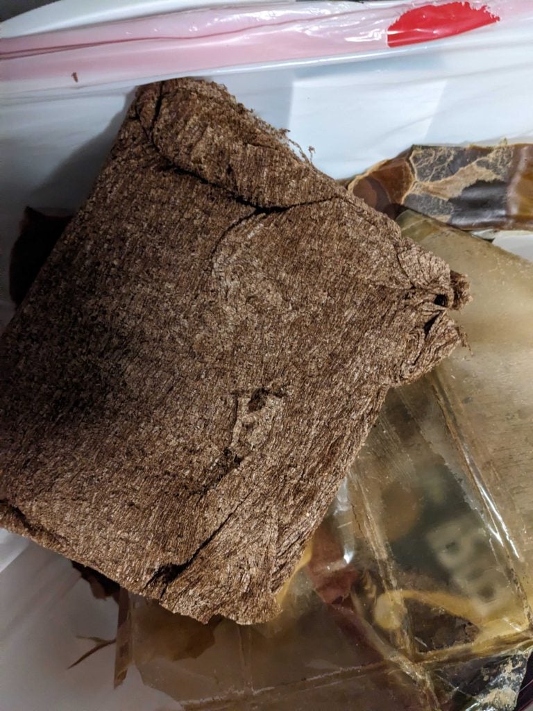
When I opened the box, the switchboard finally came into view. It was packed tightly up against cardboard (which left packing lines on the unit). It also contained this weird brown cloth-like packing material (if anyone knows what that is let me know!) –
The accessories were all in waxy and gummy waterproofed cardboard boxes. I had to use scissors to cut it open.
The results look great! I really like the switchboard, the white/tan cardboard lines not so. If anyone had an idea on how to remove them without damaging the wood let me know!
When I began to open up the switchboard, there were documents and manuals. There was a French inventory list, a French wire and circuit test, a wiring diagram, and a field manual, TM 1-330.
The wiring diagram can be downloaded as a pdf here and is 7in x 9in. The material isn’t quite computer print paper, but not cardstock. I’d say if you could find a lightweight cardstock, that’s probably the best, or just printing it off on white computer paper would also work. The diagram would be glued or taped (unsure which) to the inside access panel in the back of the switchboard.
Now to make the switchboard more historically accurate to WW2, I bought a data plate and swapped it out. I kept the old French one and just added it to my bar as kitsch.
Below is a collection of Signal Corps-related paperwork for use in WW2 Reenacting.
Radio
Templetone Model BP2-A5 Log Card – The Templetone Model BP-2A5 seemed to be some kind of morale radio for the troops. The log card would be placed under the front cover so it would show when the cover was opened. Not sure why a morale radio would need a station log card?
Print in medium-weight beige cardstock. Print on both sides of the media and cut at the crop marks to produce one Station Log card.
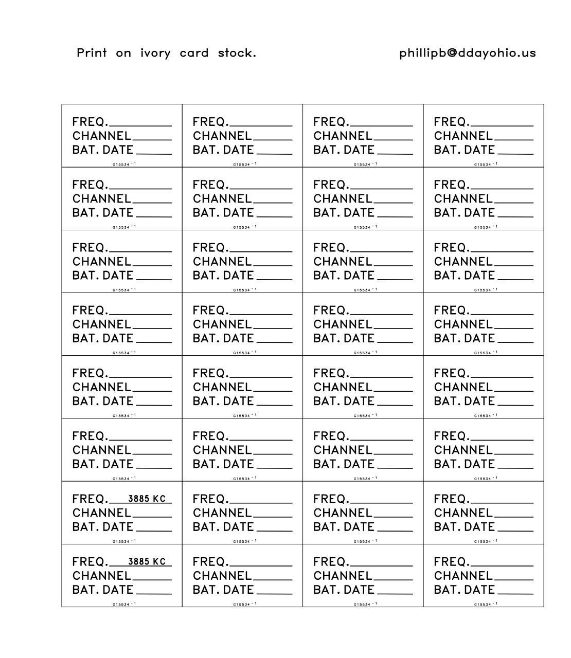
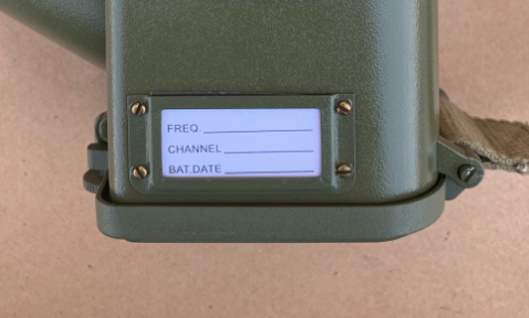
BC-611 Frequency Card – This is the card that would go into the small window of the BC-611/SCR-546 radio
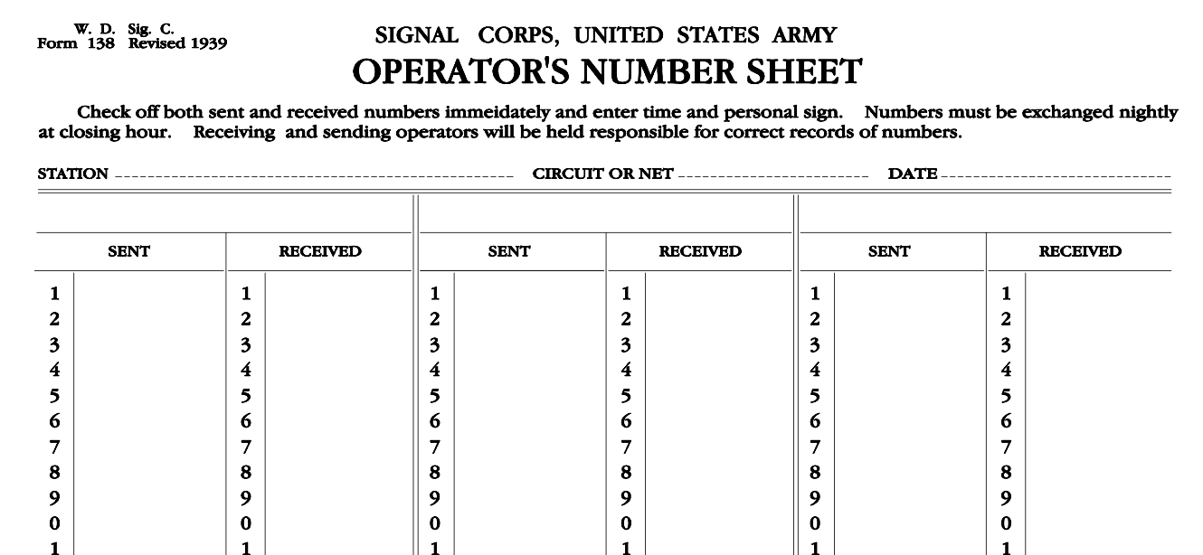
Form 138 Operators Number Sheet – Front and Back | Print front-to-back pages on natural or ivory paper and stack+trim to the same size. Run a few beads of rubber cement along the top edge to have a tear-away stack.
I’m not sure what this form was exactly used for.
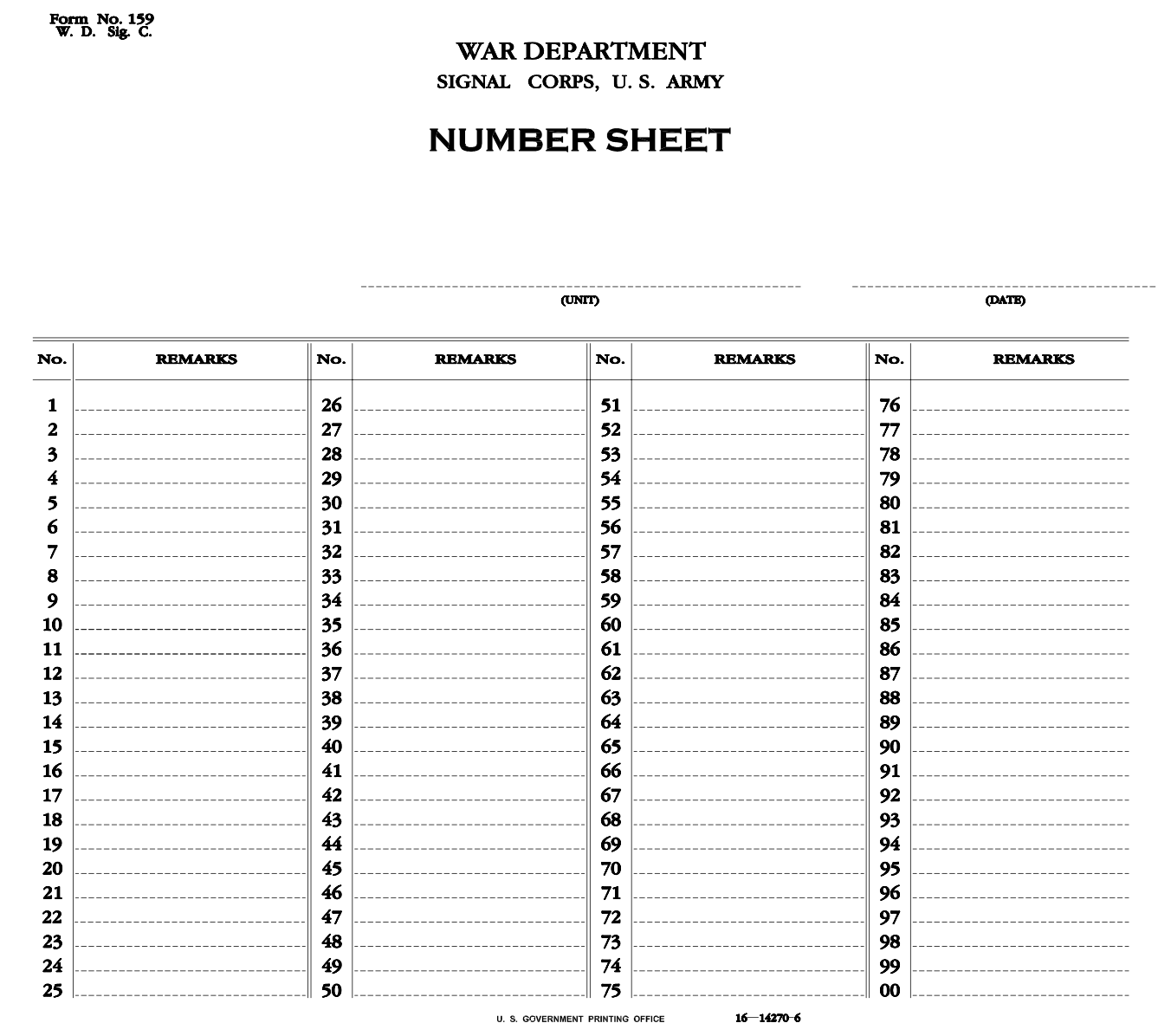
Form 159 – Number Sheet | Print pages on natural or ivory paper and stack+trim to the same size. Run a few beads of rubber cement along the top edge to have a tear-away stack.
I’m unsure what this was exactly used for.
Telephone
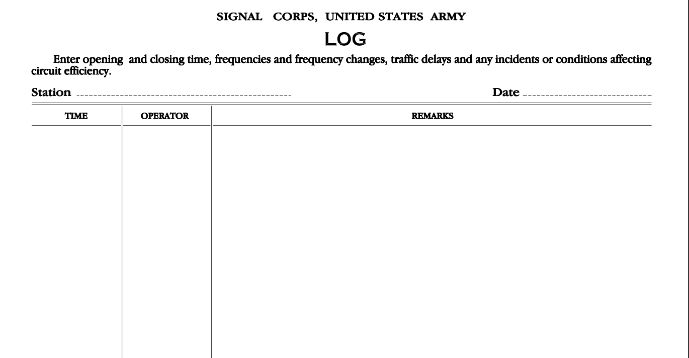
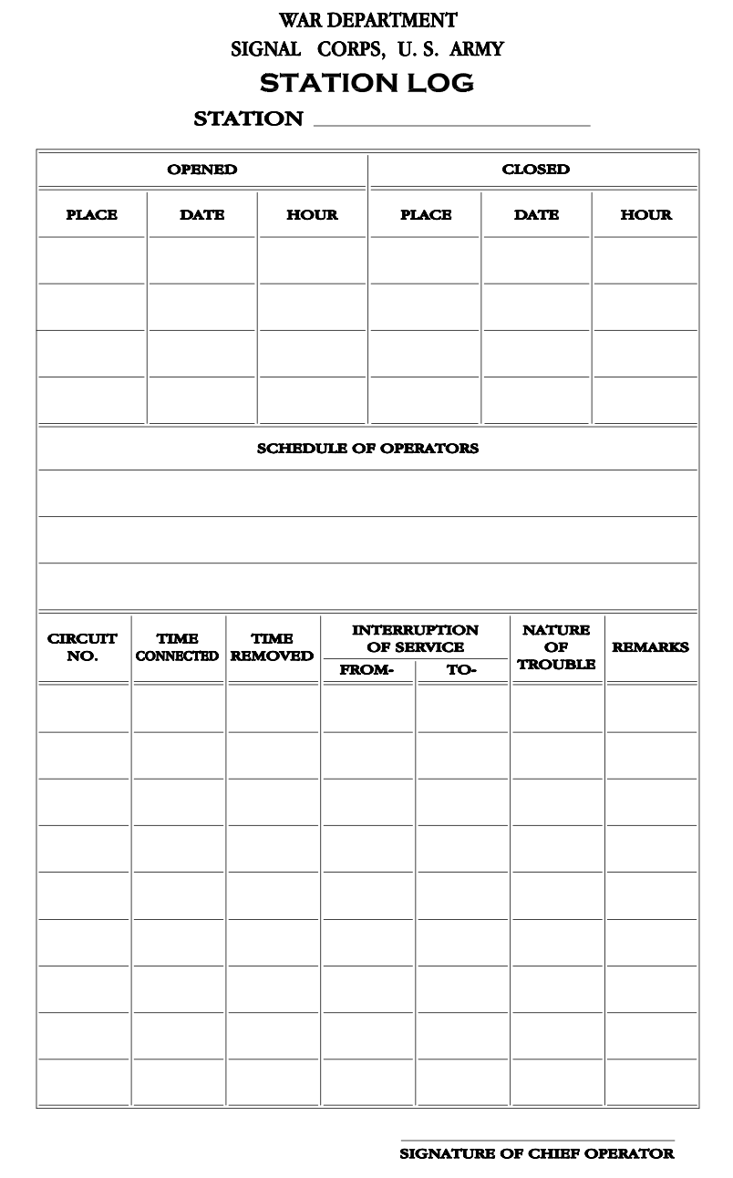
Signal Corps Station Log – Signal Corps paperwork to record traffic at what appears to be a telephone station. Form number unknown.
Print pages on natural or ivory paper and stack and trim to the same size. Run a few beads of rubber cement along the top edge to have a tear-away stack.
Other
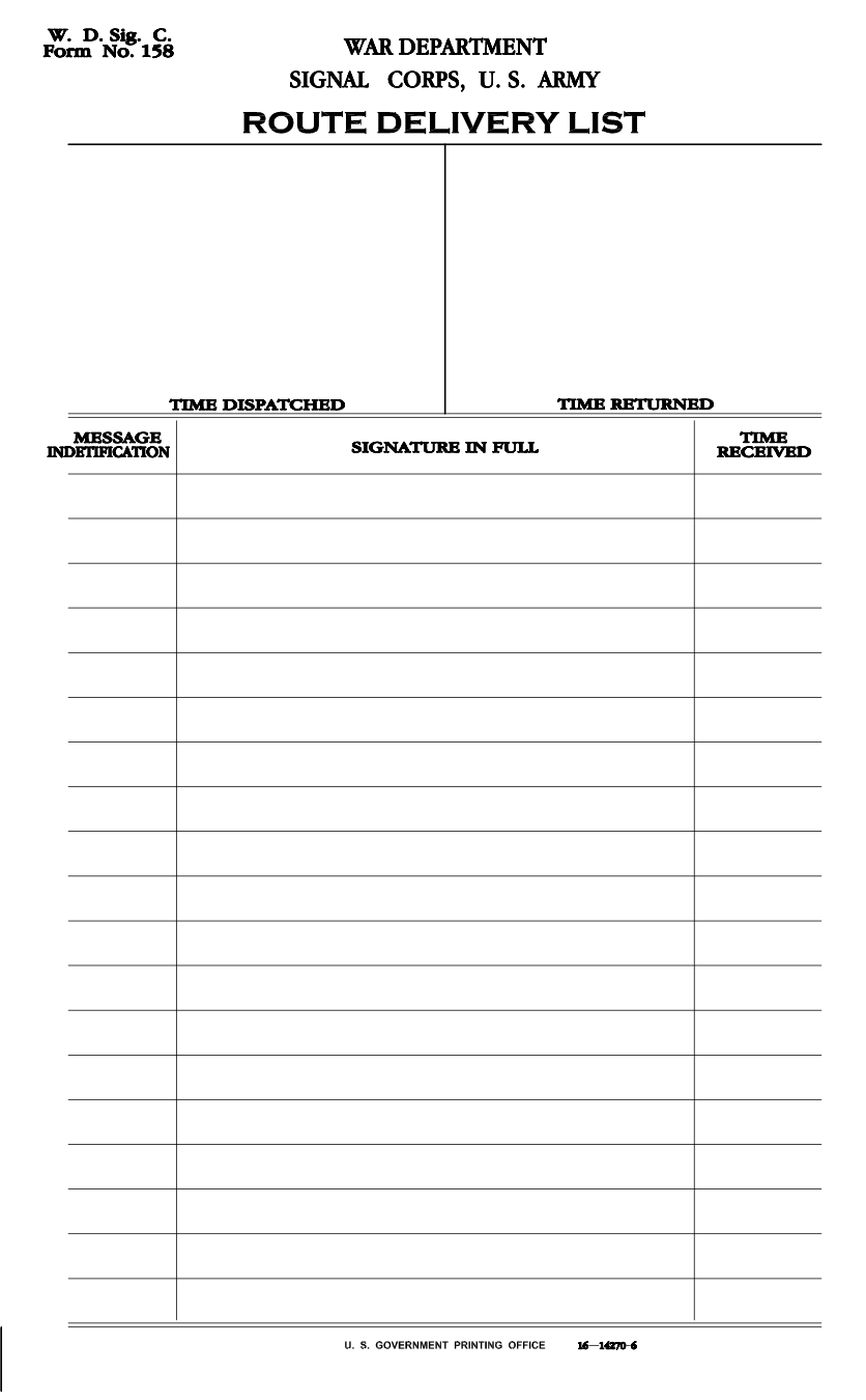
Form 158 – Route Delivery List – Signal Corps form for delivering messages. Print 25 pages on natural or ivory paper and stack and trim to the same size. Run a few beads of rubber cement along the top edge. You’ll have a tear-away pad of 50 sheets.
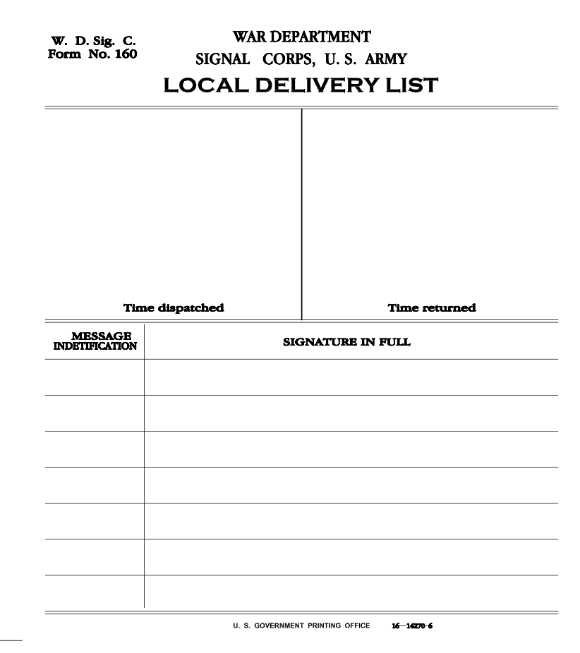
Form 160 Local Delivery List – Signal Corps form for delivering messages. Print 25 pages on natural or ivory paper and stack and trim to the same size. Run a few beads of rubber cement along the top edge. You’ll have a tear-away pad of 50 sheets.
A “local delivery” seems to connect fewer points.
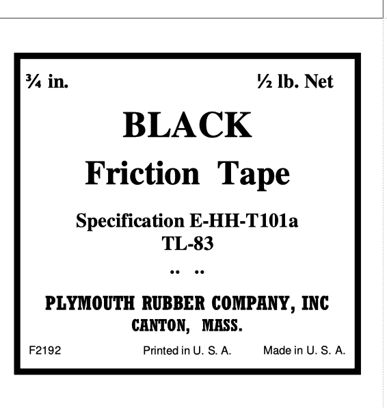
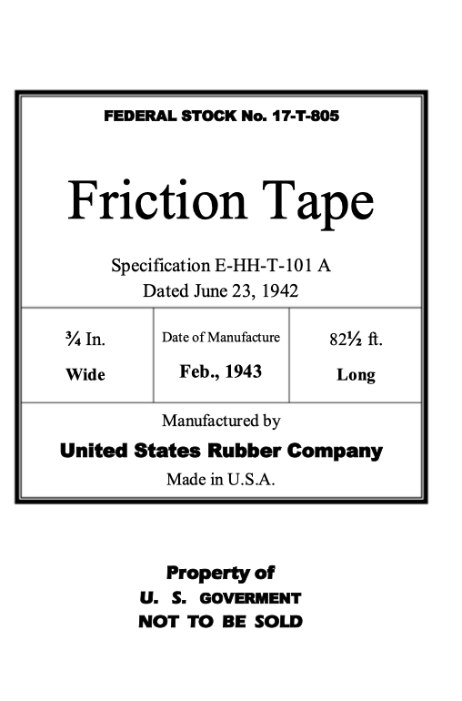
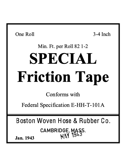
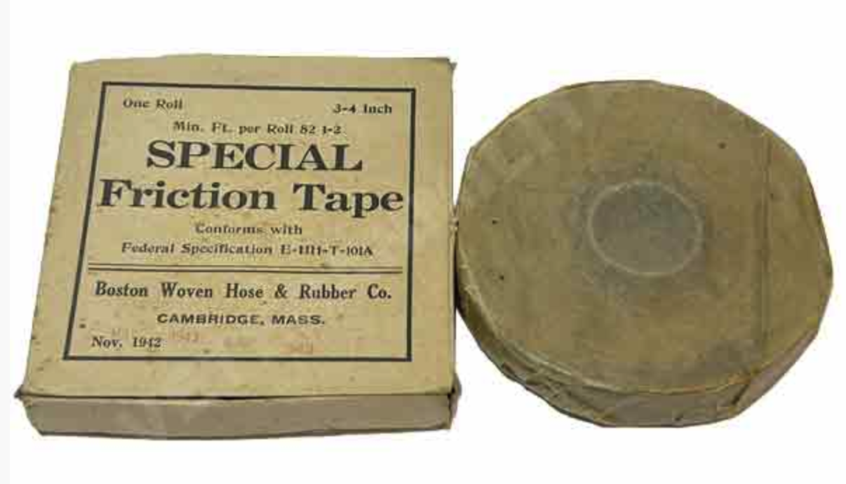
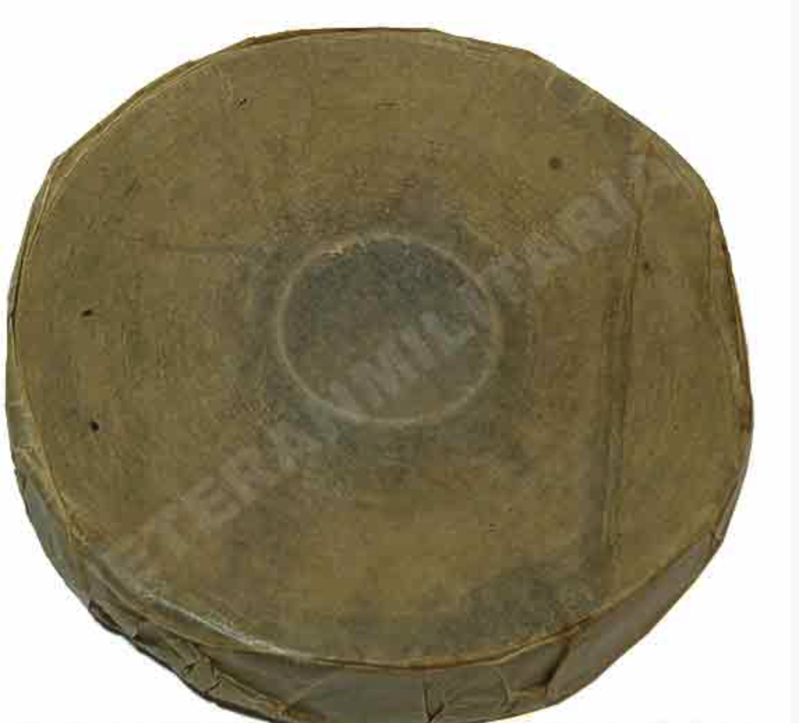
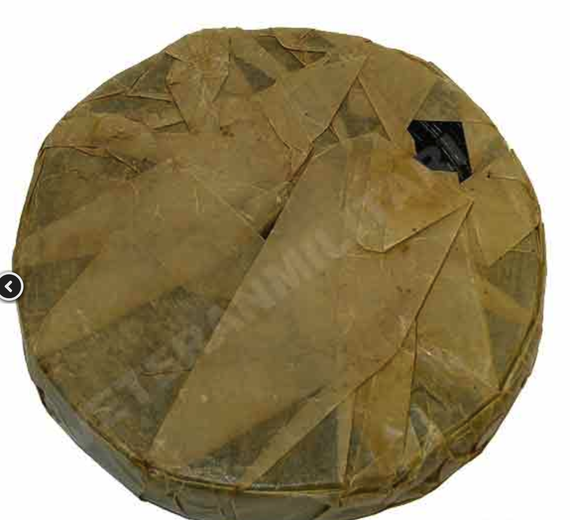
Friction Tape Boxes – Friction tape is a woven fabric tape. The zip file contains three kinds of boxes.
Friction Tape Feb 1943 Specification E-HH-T-101a
Special Friction Tape Jan 1943 Specification E-HH-T-101a
Black Friction Tape TL-83 Specification E-HH-T-101a
Best I can tell, all friction tape was black and wrapped inside a brown, waxy sheet. Since all the boxes have the same specification, I’m assuming there’s no difference. Additionally, TL-83 is the nomenclature for the tape, and there appears to be no other friction tape nomenclature that might suggest a difference among them. I think it’s just the manufacturer’s choice on how to describe the contents of the box.
Message Book M210a Front and Inside – A printable PDF file for the M201a message book. This book would be used in a message center. It would be unlikely to appear in a map case. You can download thefront+back here and the insides here.
Print on regular paper and then trim to size. The book has overall dimensions of approximately 6-1/8″W x 4-1/4″H x 1/2″ thick. Inside the book are 25 each triplicate message forms for regular use, three each duplicate forms for carrier pigeon use, and 25 sheets of tracing paper. The back cover has an extension that can be placed under the topmost form, so that it can be filled out without marking the carbon copies of the following forms. The book also includes instructions for its use and a list of authorized abbreviations.
For best results, print on 8-1/2″ x 11″ US letter-sized paper with no scaling. Finished forms should be 4.75in wide by 4.25in tall.
When cutting it out, save 1/4 inch of space on the left-hand side. That way, the staples don’t go through the message part.
I’m not sure if anyone is reproducing these, but if they are, I’ll add a link. Note that this only includes a single blank message form and not the carbon copies or map overlay.
Now there’s also an M 210-B message book, which looks like it came out in late 1944. This is according to the Signal Corps Technical Information Letter, Nov 1944 No 36. The major differences are some measurement tools on the front cover, the removal of the pigeon forms, and the map overlays. This was all done to help speed up the message processing, as it was found that soldiers experienced difficulty removing the copies in the M210a book.
There’s also an M-105-A message book. I’m not sure what the difference is. If I find out, I’ll write about it.
Signal Corps Technical Information Letters
Signal Corps Technical Information Letter No 18 – May 1943. Outlines new training methods, procedures, and equipment. One interesting story is how local police captured an illegal pinball den and donated the machines to Ft. Monmouth to be used as needed.
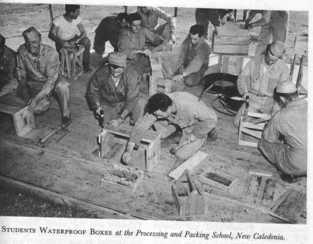
Signal Corps Technical Information Letter No 36 – Nov 1944. Outlines new training methods, procedures, and equipment. Discusses the fungi and moistureproofing techniques (which is some kind of lacquer spray), as well as the Silica Gel, used to pack equipment, and an anti-radio jamming exercise, among other interesting and nuanced signal corps minutiae.
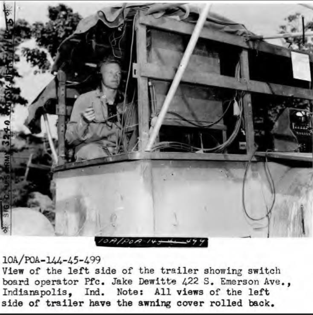
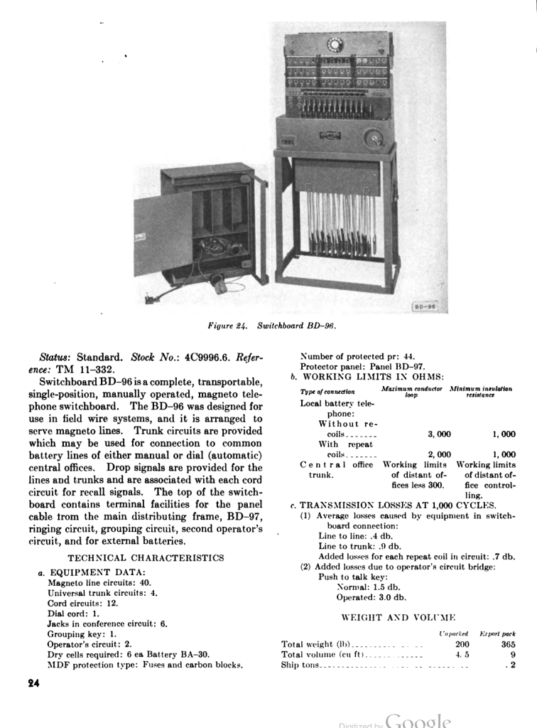
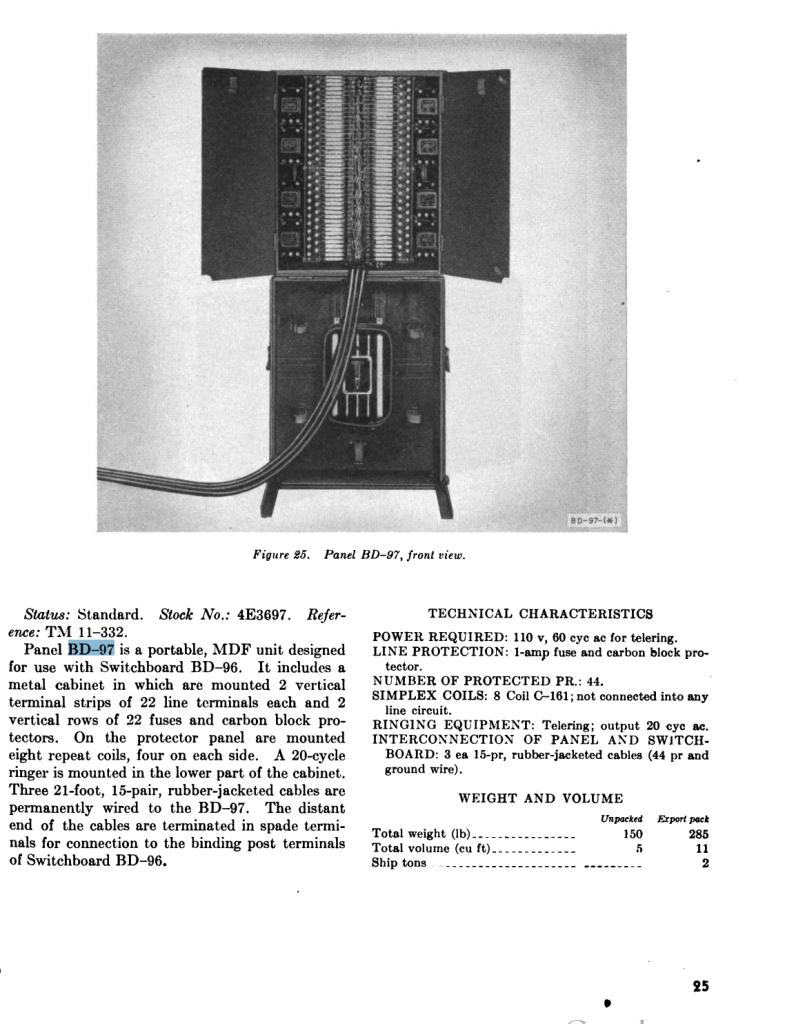
27th Signal Company Switchboard Trailers – During the Phase 1 Nansei Shoto Operation on Okinawa, the 27th Signal Company of the 27th Infantry Division created a special trailer to house a BD-96 switchboard, and its BD-97 panel, test sets, EE8 field phones, and other incidentals required to operate a BD-97 switchboard in a combat operation. The BD-96 is used to run up to 40 lines into it.
The trailer was used to be as mobile as possible during the operation. Being mounted in a trailer makes it so.
This type of configuration may have been used at the Battalion or, more probably, at the regimental level.
TM-184a Terminal Board Fabrication – This is a PDF that shows the schematics of how to fabricate the TM-184a terminal board. It is used as a terminating or test point in tactical field wire systems.
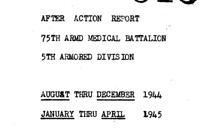
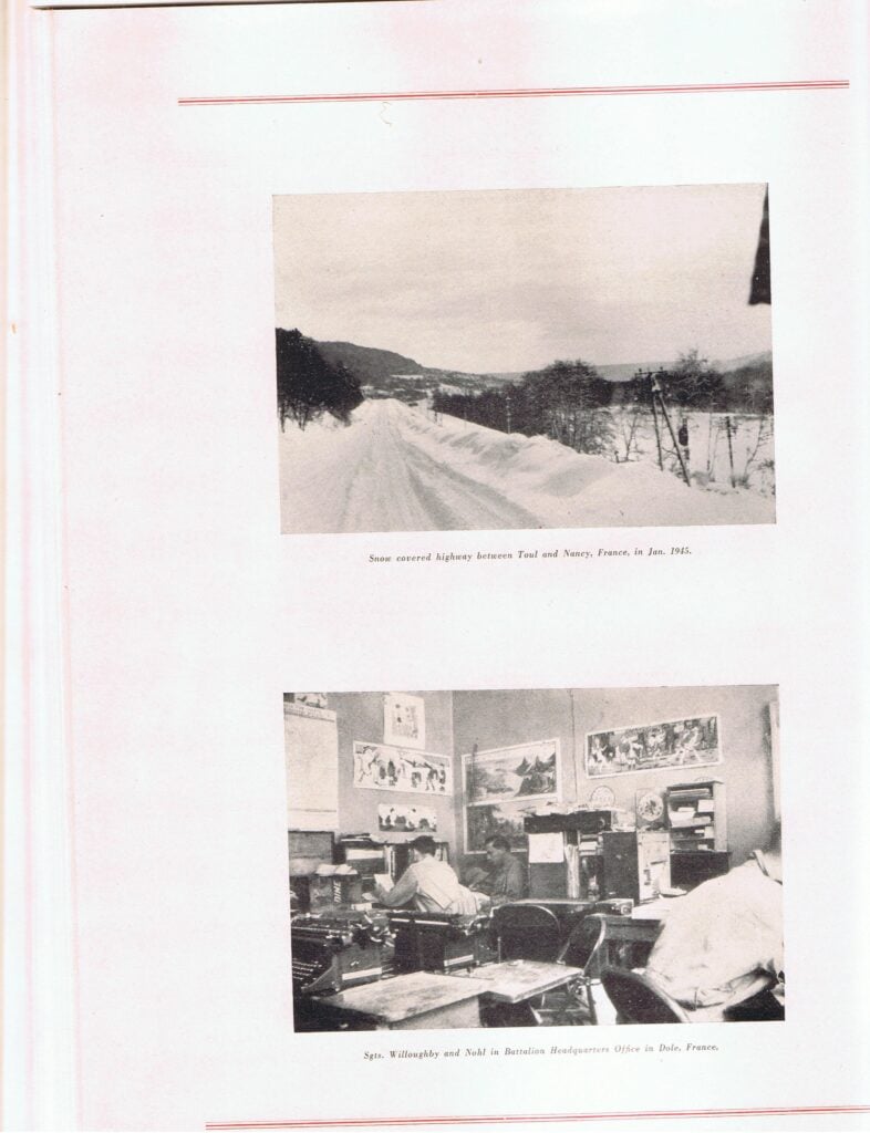
It covers August 1944 to May 1945 and includes A, B, and C companies. Mostly a mention of movements, events, losses, and personal changes.
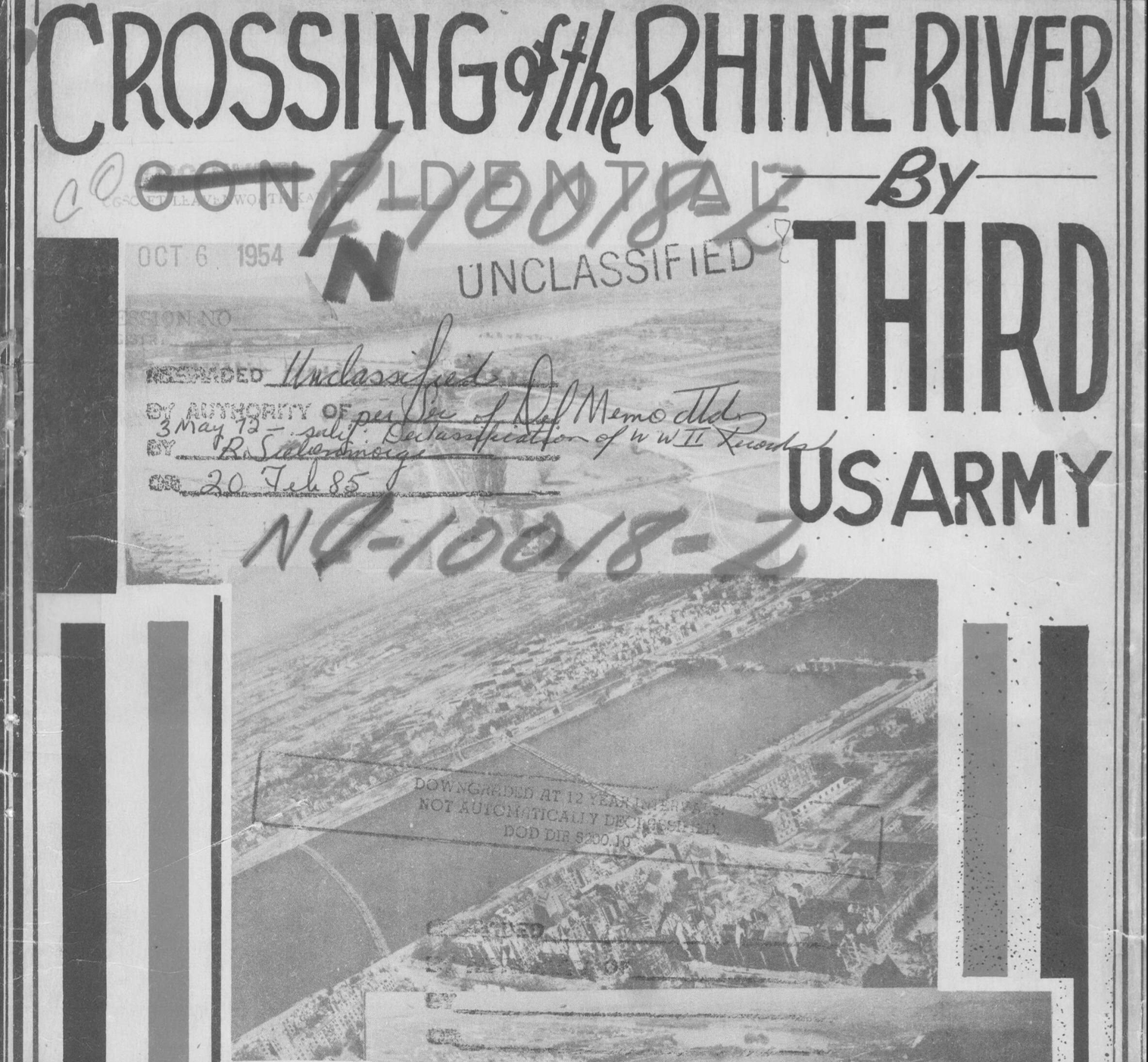
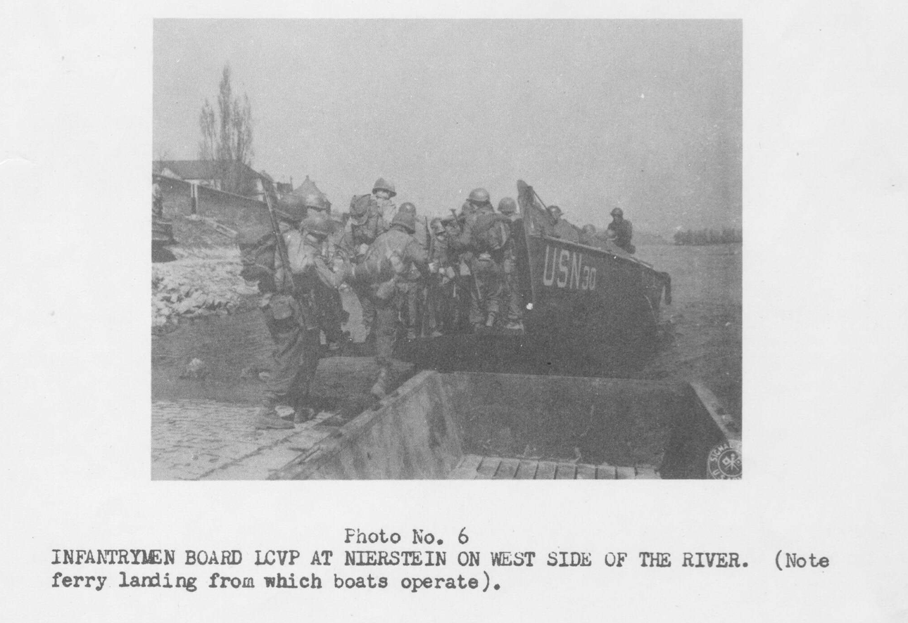
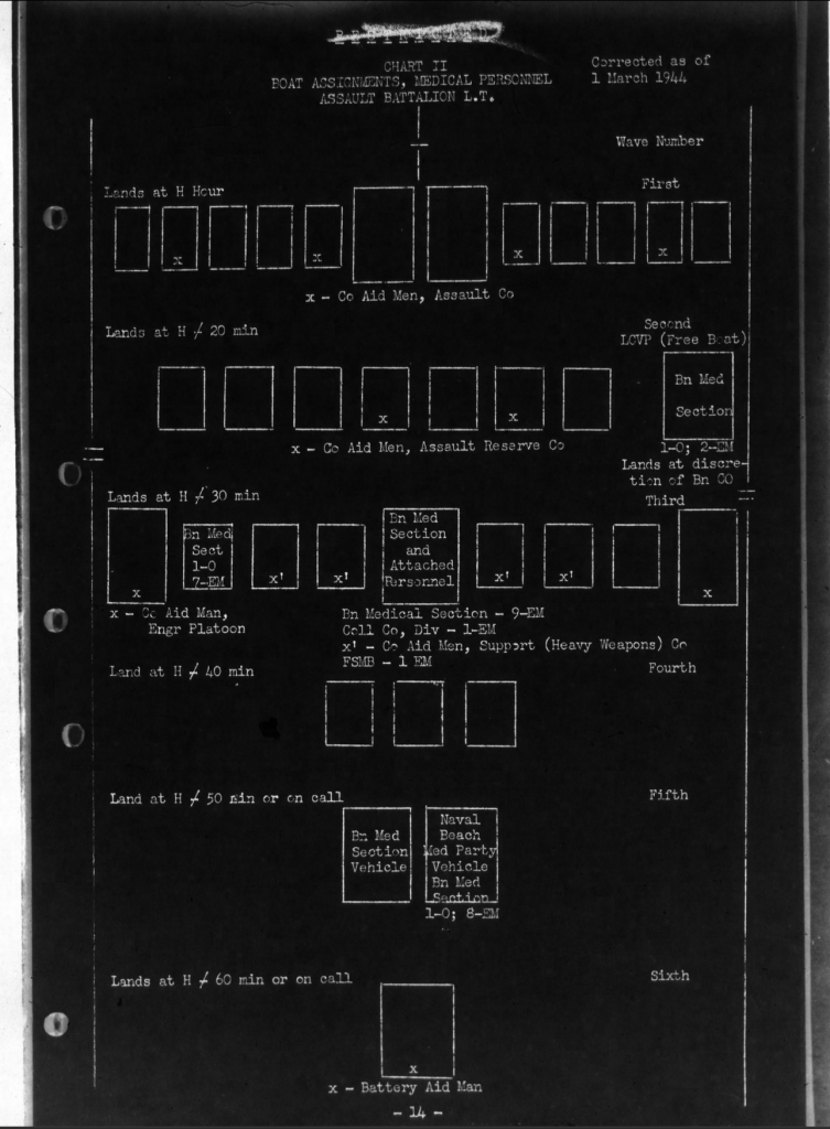
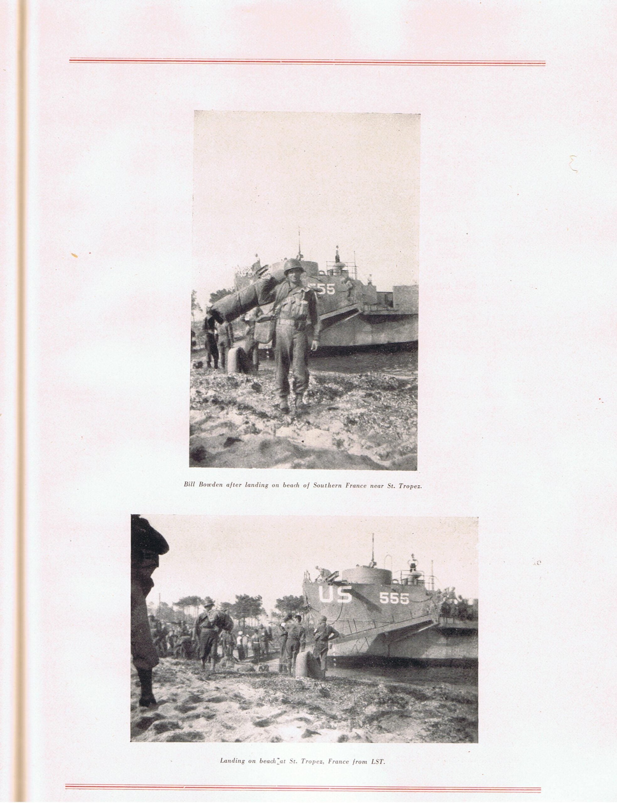
Crossing the Rhine River by the Third Army – Documents the landings at the Rhine River. Storm boats and assault boats were used at the start, and then several hours later, LCVPs were brought up. Includes images.
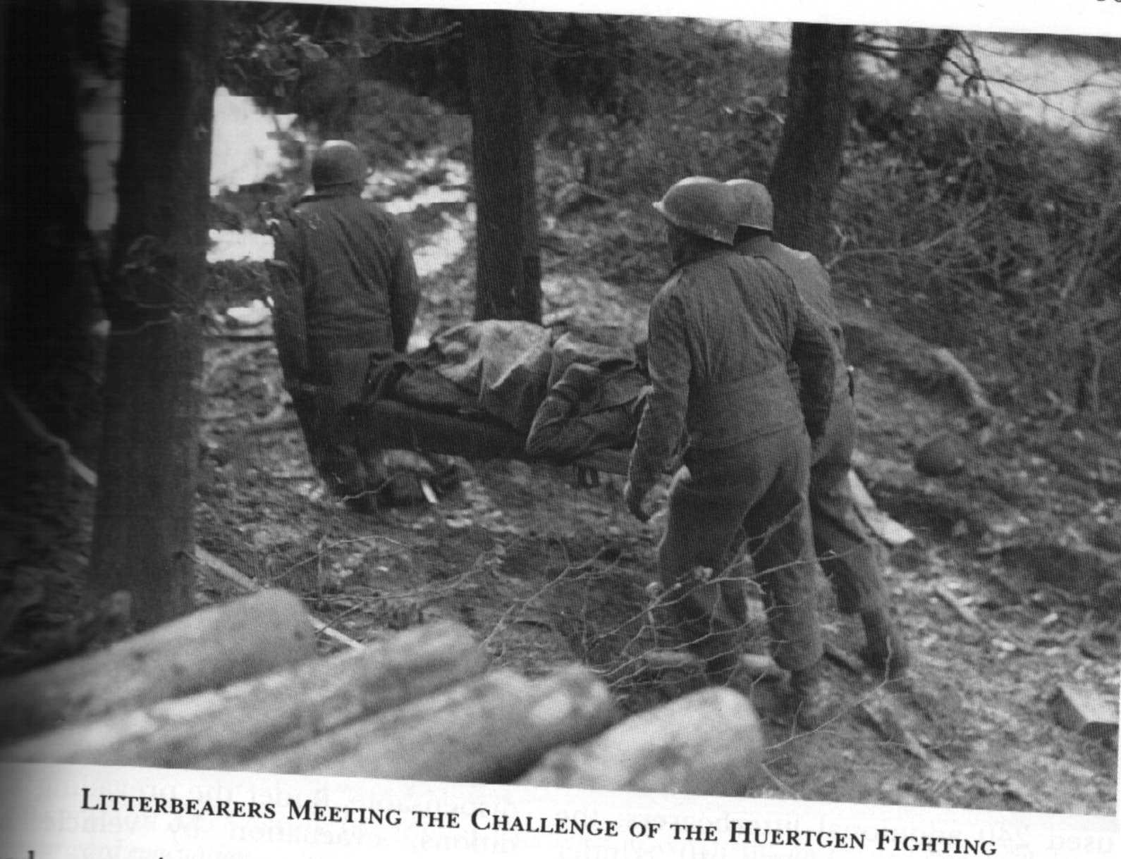
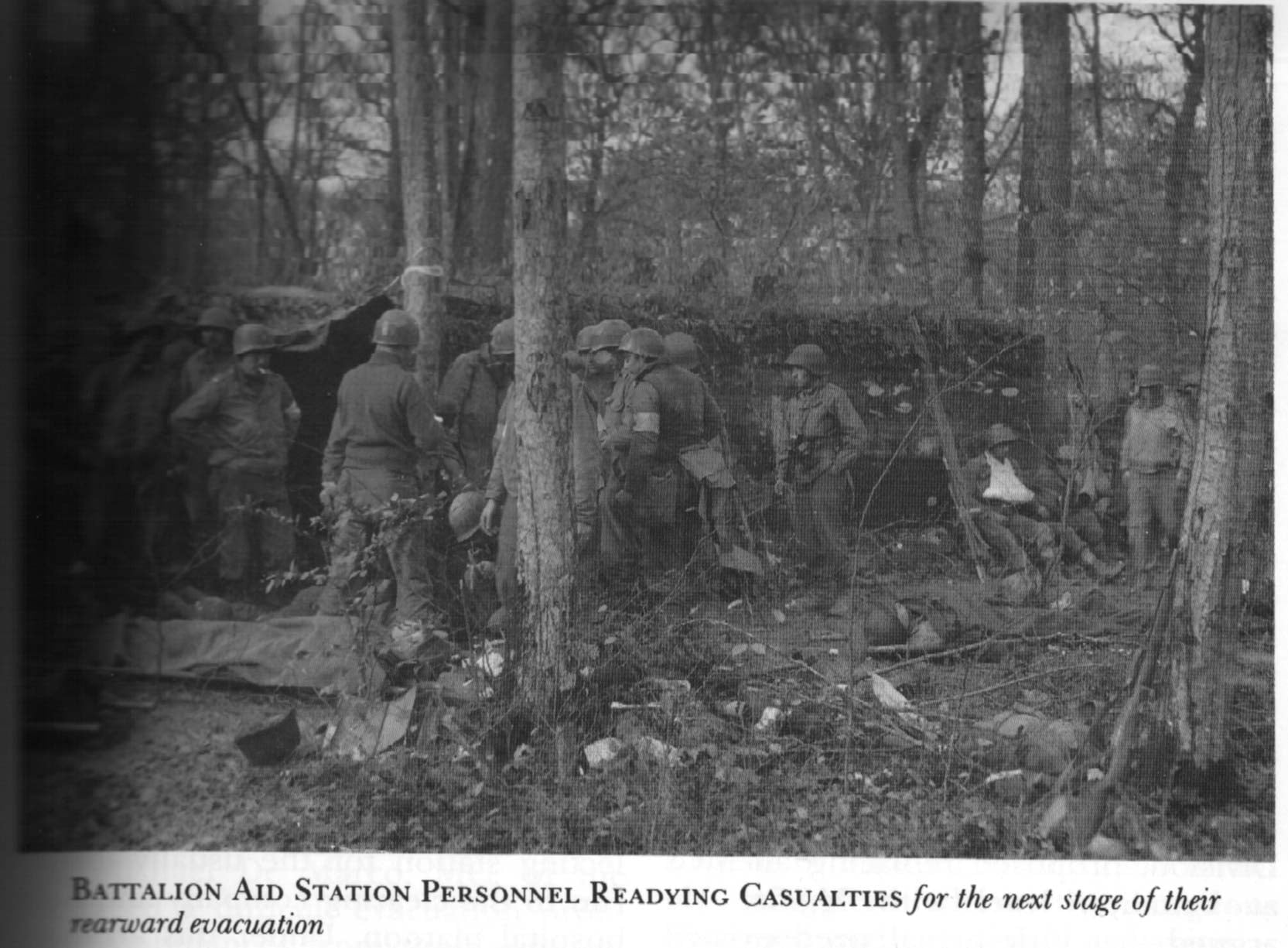
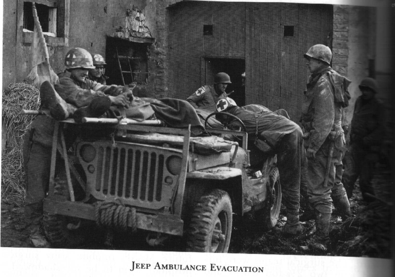
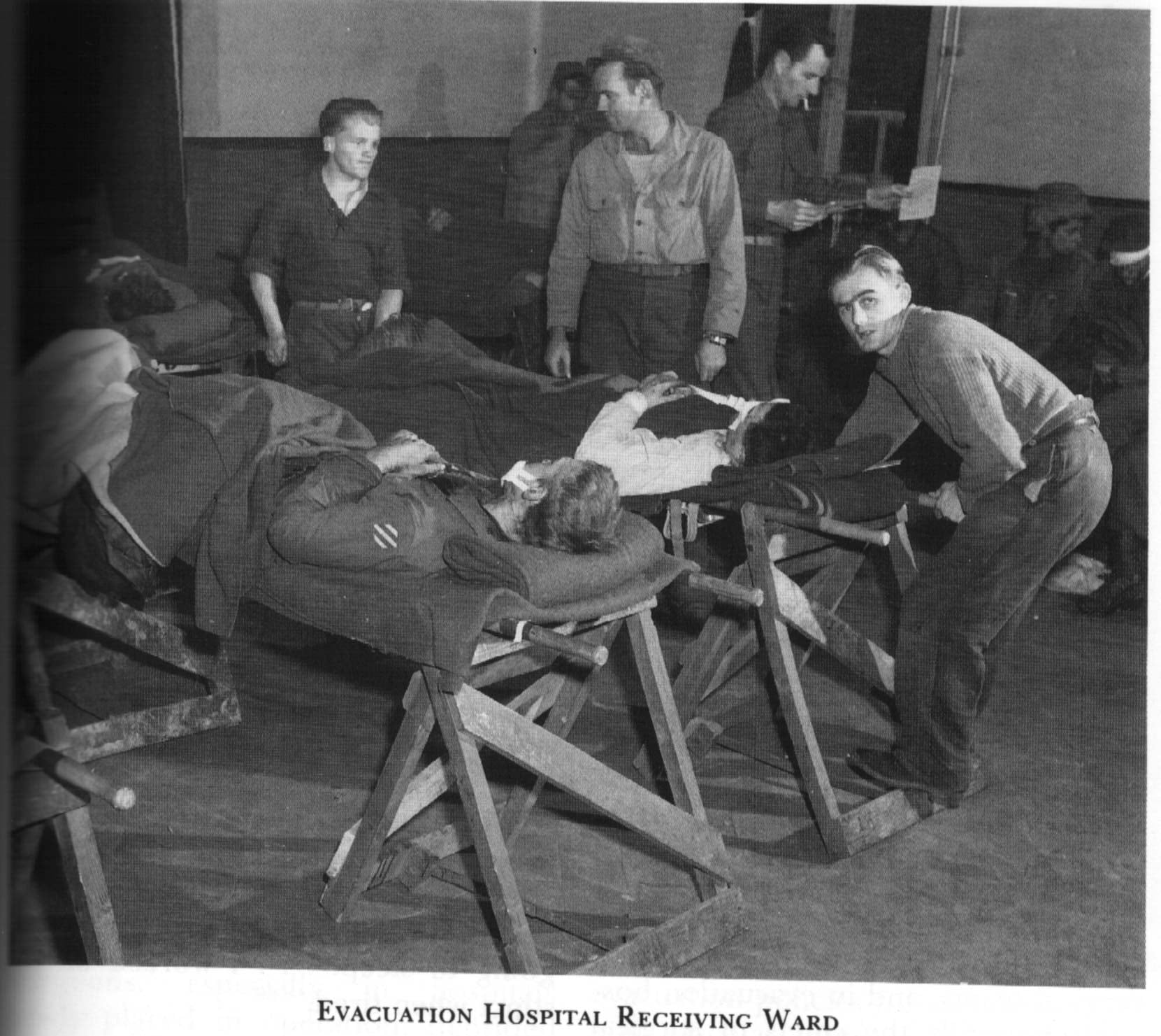
One interesting thing is that it goes into detail about how operations change as the beachhead is expanded. Essentially, the wounded are pooled and treated during the initial 30 minutes. After an hour, a battalion aid station is created. After 3 hours, additional battalion aid stations are created as the beachhead expands forward, close to the front. You also get a primary collection point for all wounded. 12 hours, you get vehicles such as jeeps and ambulances. After about 4 days, you get evacuation hospitals.
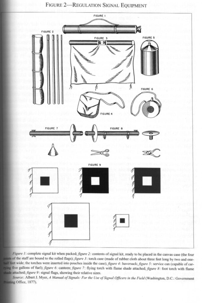
Communications in Assault Operation – Nov 1943 from the US Assault Training Center ETOUSA. Outlines what teams have what kinds of equipment, where they are positioned, and what net they operate on. Essentially, how to have an integrated communication network across visual (ie, flags), wire, and radio between infantry, tanks, field artillery, naval gunships, and aircraft.
Infantry Division Signal Company 1st Signal Company 2nd Signal Company 4th Signal Company 9th Signal Company 29th Signal Company 90th Signal Company Armored Division Signal Company 142nd Armored Signal Company Airborne Division Signal Company 82nd Airborne Signal Company 101st Airborne Signal Company
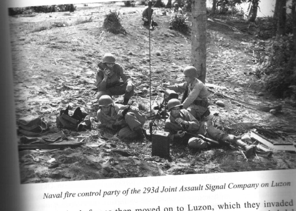
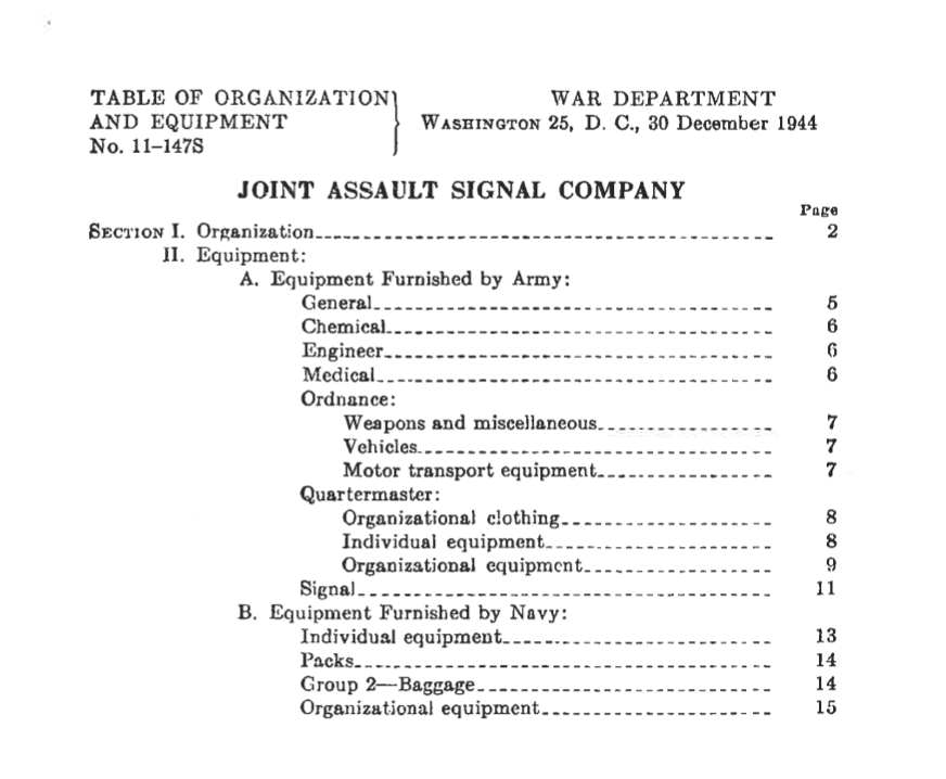
Joint Assault Signal Companies Engineer Brigade Group Signal Company 286th Joint Assault Signal Company 293rd Joint Assault Signal Company 294th Joint Assault Signal Company
Signal Service Company 3251 Signal Service Company 3252 Signal Service Company
Corps Signal Battalion Signal Battalion 50th Signal Battalion 56th Signal Battalion
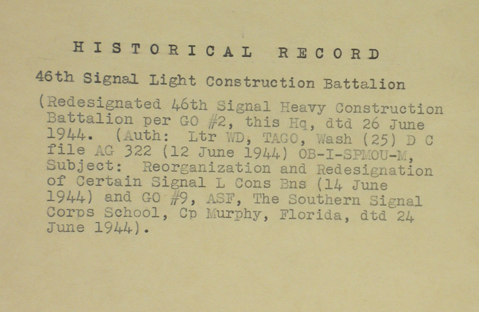
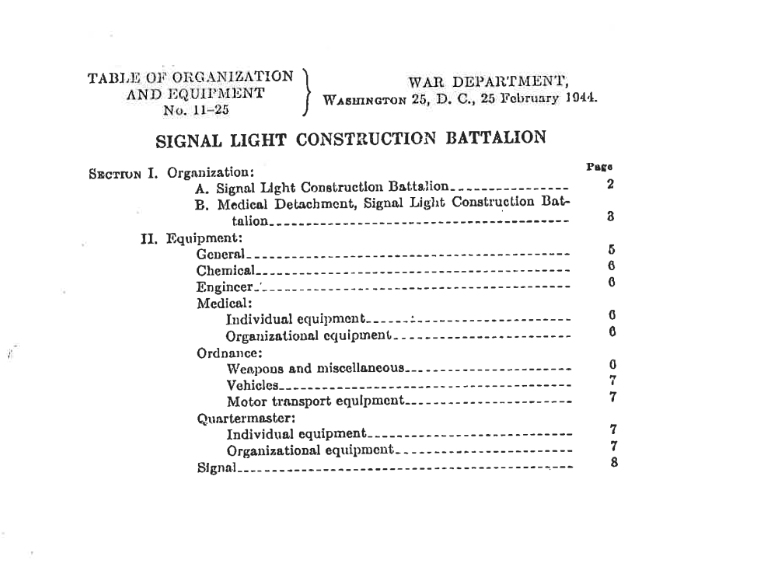
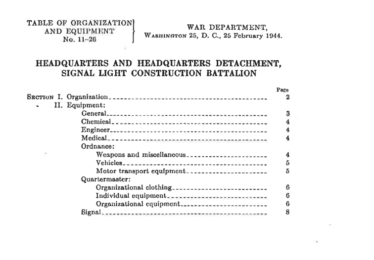
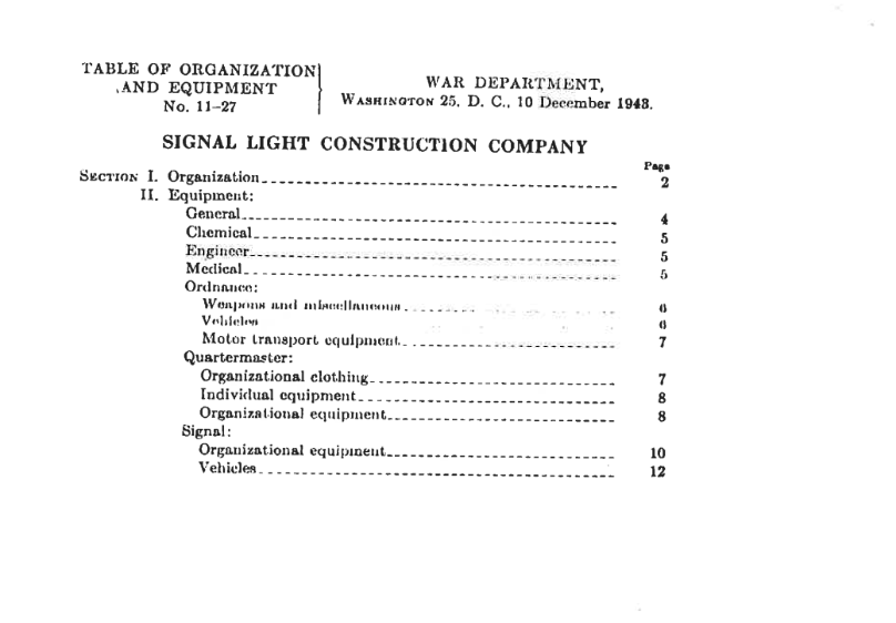
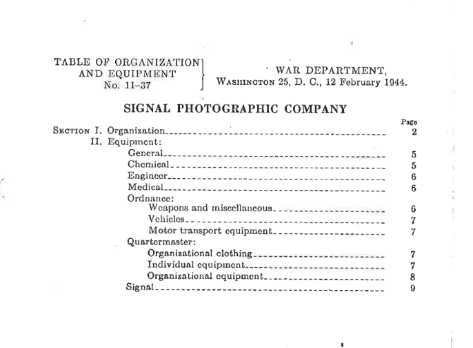
Signal Construction Battalion 29th Signal Construction
Signal Sections 1st Army V Corps VII Corps VIII Corps XIX Corps
It’s noted that the SCR-536 was to be used at the company level, either communicating across companies or communicating down to lower echelon units like platoon, section, or squad.
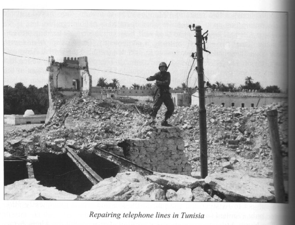
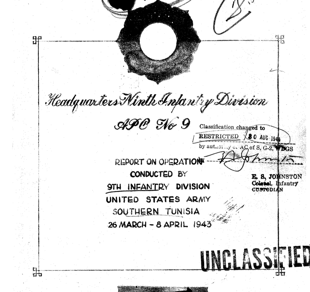
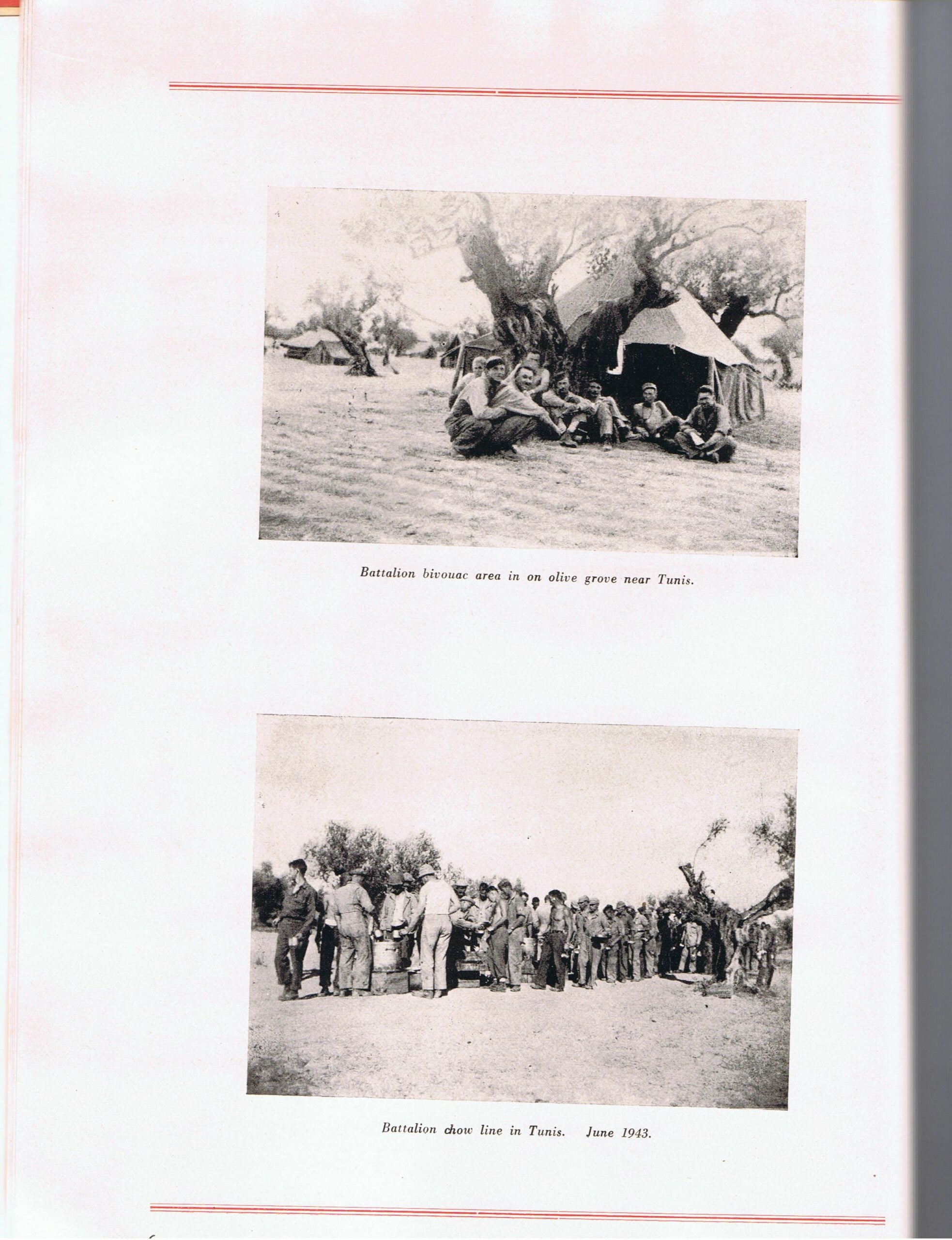
Operational Conduct of the 9th Infantry Division Southern Tunisia March to May 1943 | A fascinating review of the 9th Infantry Division in North Africa. A little “slice of operational life”. The analysis at the end is worth reading. At one point, they had to put the band and other service troops to work as litter bearers. Also, they had up to 22 and 32-mile wire circuits laid out, and switchboard tubes were blowing due to the heat. Interestingly, they had attached to them the Corps Franc d’Afrique, consisting of (a) 3 Infantry Battalions (b) 1 Marine Battalion (c) 4 Tabours of Goums
One big issue was supply. The units responsible for loading up the ships with supplies simply were not able to assemble all the tonnage required by the Signal Corps units in the time frame needed. So items that were supposed to be on a ship scheduled to land during the 7th echelon instead landed in the 12th. Indeed, telephone poles didn’t appear until 60 days later. Fortunately, units were able to improvise and press into service different pieces of equipment (such as substituting different gauge wire) along with reusing captured enemy and civilian wire/equipment.
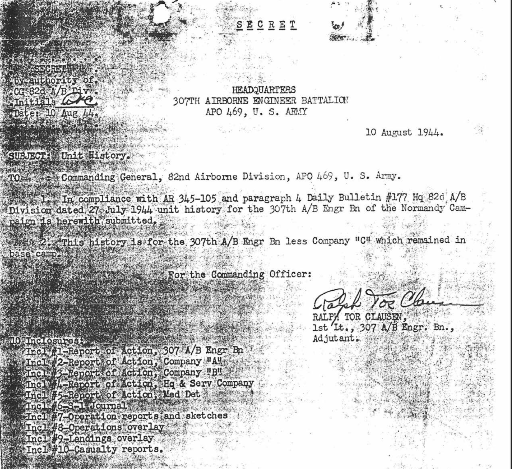
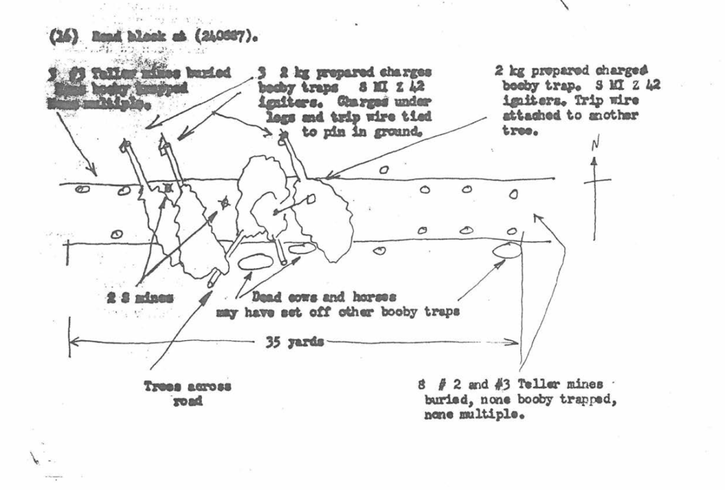
What I find neat about it is the hand-drawn diagrams that show the landing areas for the battalion, as well as an outline of how the Germans blocked roads with Teller Mines and booby traps. The S-1 Journal of events that happen throughout various days is a neat read, too.
The document also reports on the 307th Medical Company, however, more information about this unit can be found at the link.
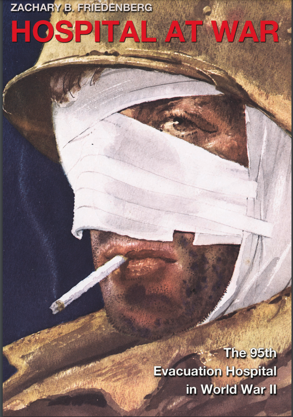
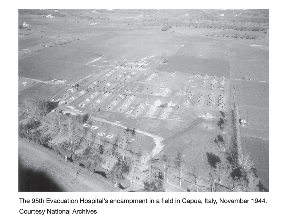
33rd Field Hospital Nursing Report 1944 – Describes the events of the 33rd Field Hospital, which landed at Anzio and was part of the bombing raid on the 95th Evacuation Hospital (the 33rd was across the street from it) on Feb 9th that killed 20 and wounded over 50.
Describes a few humorous incidents, such as Unit C thinking of a Collecting Company (which would be tasked with moving wounded from the front lines to the battalion aid station) for a Clearing Company (who would be tasked with triage of wounded, deciding which kinds of hospitals they go to, and moving them there). They ended up quite near the front line before doing a turnaround!
Signal Corps personnel, training, and command and admin structure study number 112 – A report on the training and administrative structure, along with recommendations.
Signal Corps Operations in the ETO Study Number 111 – Discusses issues with wire, radio, facilities, railway, pipeline, and the Press. The Signal Center (ie a larger “message center”), Photography, and Frequency allocation, and provides recommendations.
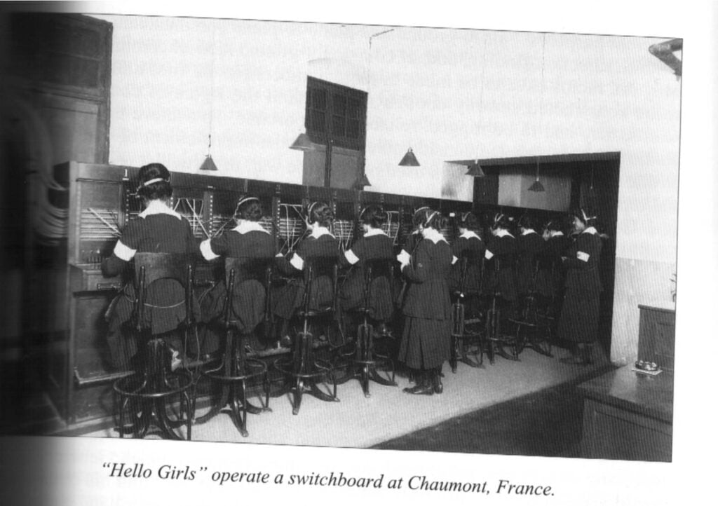
One interesting note is that regarding men using switchboards,”…a truth long recognized by commercial telephone companies again became evident; that men do not have the finger dexterity nor are they temperamentally adapted for efficient operation of large switchboards. As female operators from the Women’s Army Corps became available, they took over the switchboard operation…”
Psychological Warfare in the European Theater of Operations Study 131 – 1945 | A review of psychological operations in Europe. Discuss gathering intelligence and distributing it. Makes mention of problems and issues related to using radio, ariel leaflets, artillery leaflets, and speakers to spread propaganda to induce the enemy to surrender.
One interesting note is a section on mounting a loudspeaker external to a tank.
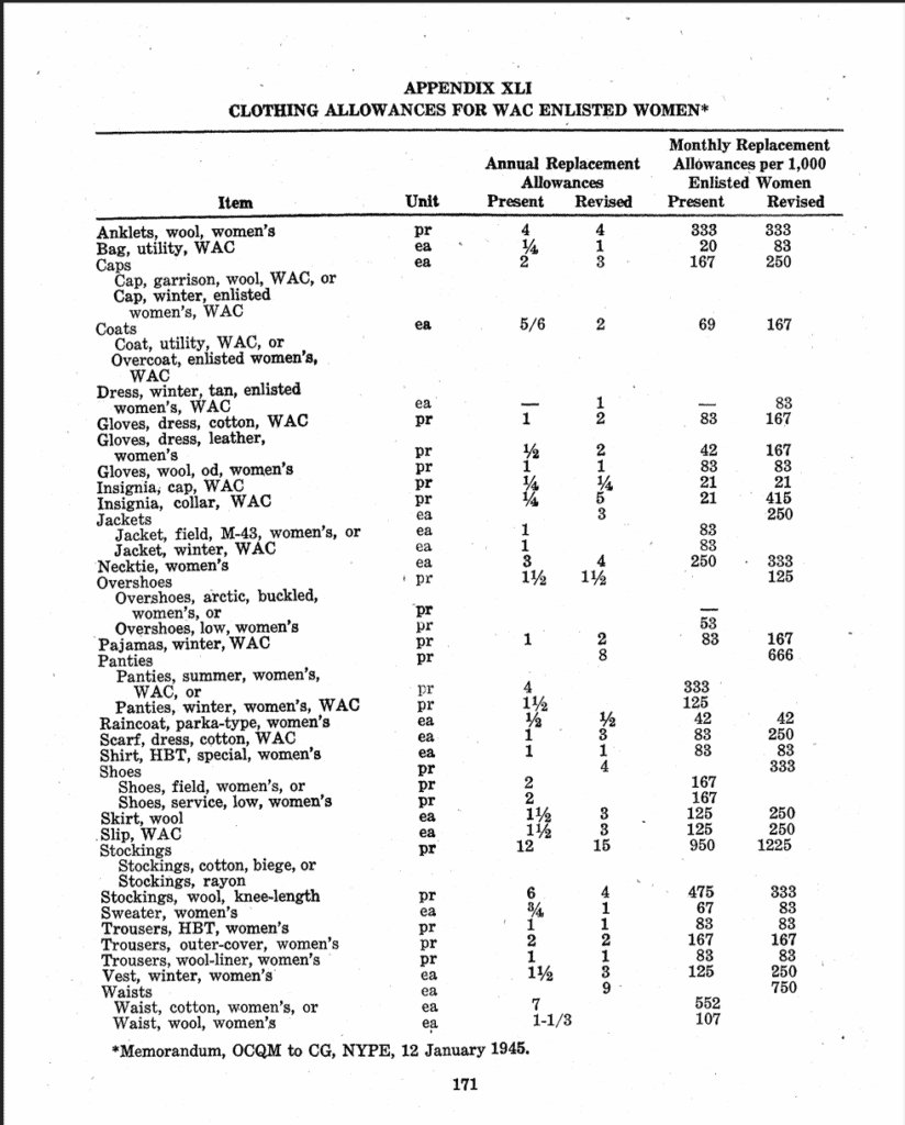
Operational Study 6 – Combat Replacement Factors Nov.1945 – A series of charts that tries to model the replacement factor for various pieces of organizational equipment between June 1944 to June 1945 in the ETO per 1,000 men per 30 days.
For example, the M1943 field jacket had close to a 20% loss rate and the M1926 utensils had a 10% loss rate.
Hitler Jugend – SHAEF Handbook – 1944 | Outlines the history, structure, organization, and uniform of the Hitler Youth organizations. As well as commanders and the location of camps and schools.
Hitler Youth drew from all parts of Germany’s conquered areas and was divided into different branches such as Hitler Youth Army, SS, Marines, Navy, AirForce. They also had a cavalry group, but it looks like it was disbanded before the start of WW2.
Also included are the opposition groups, such as Edelweiss.
Major Teletype Networks in Europe Jan 1945 – Includes a directory, station names, and call signs. Teletype is the name of the corporation that produced machines that produced specialized communication devices like Teleprinters. These are printers that can send and receive signals and then print out a message.
These “Teleprinters” are the classic news printer sound of “fast clacking metal keys” you may hear in the background of some news reports.
The US Army created a network of these machines in Europe to help with communication.
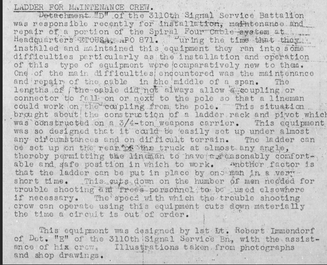
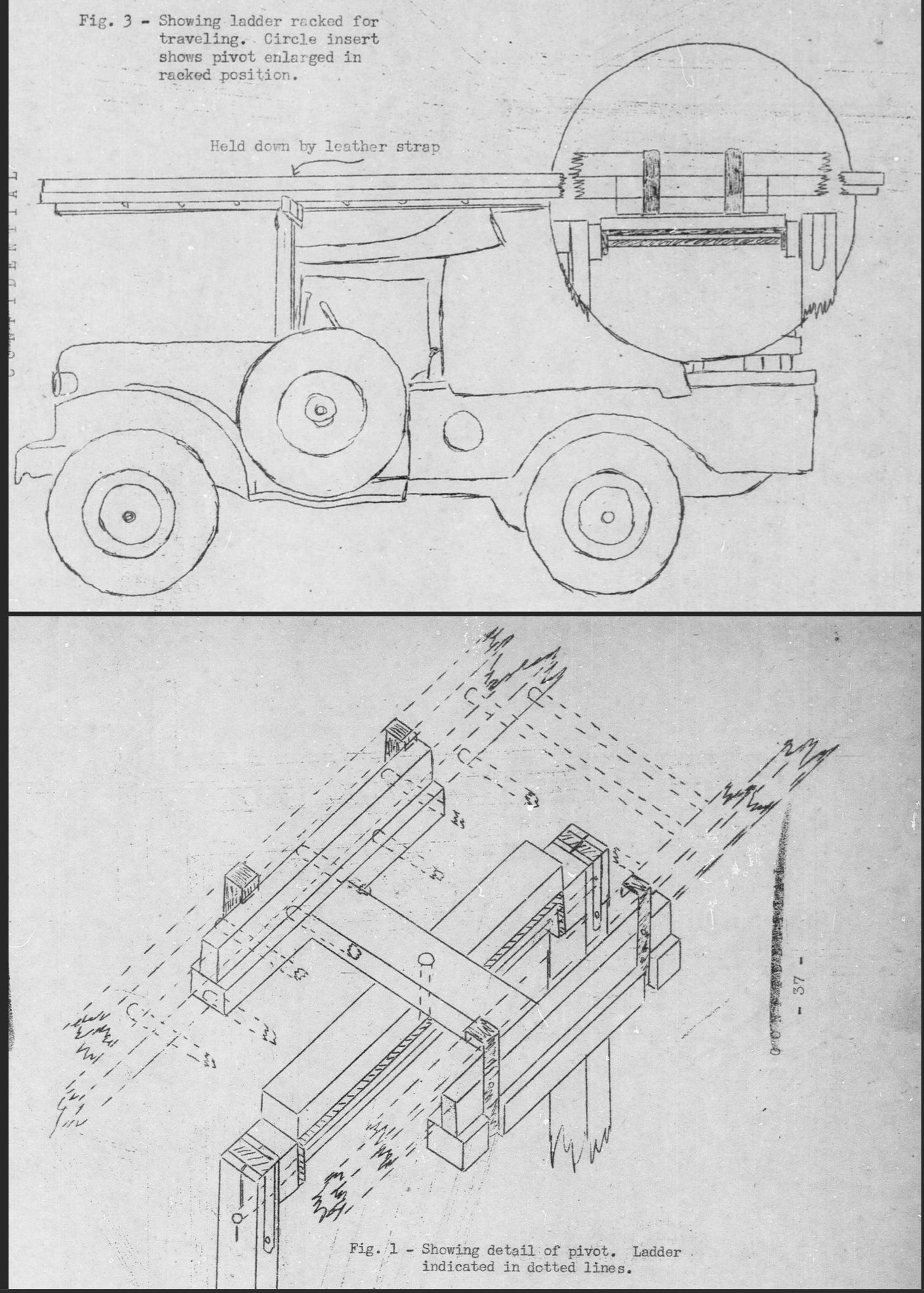
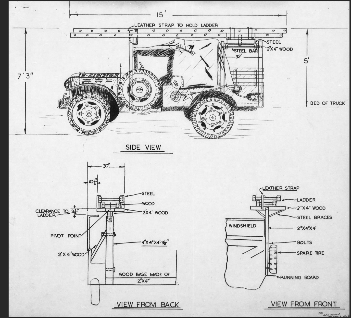
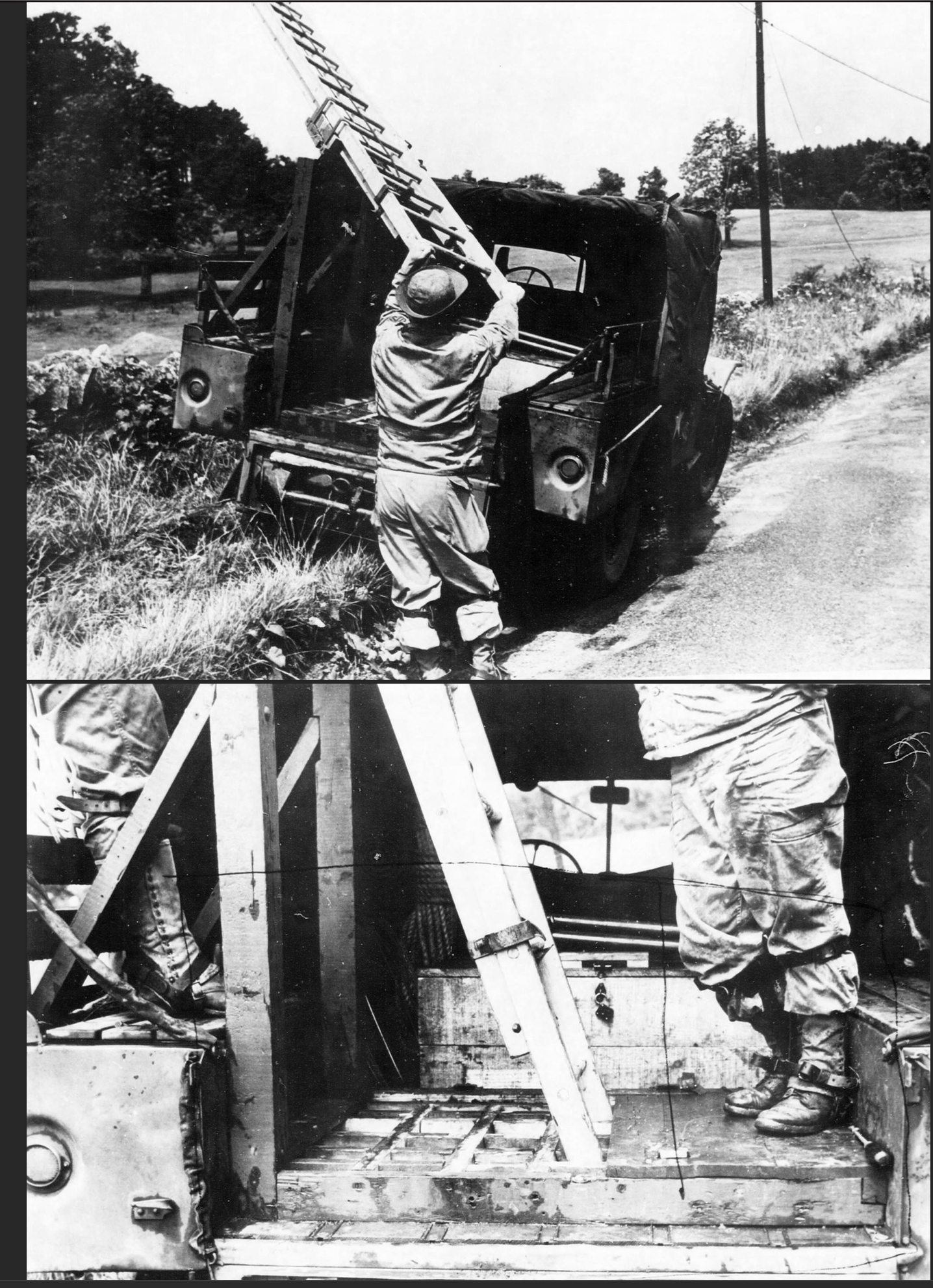
Ladder Pivot Modification to Dodge WC – Detachment D of the 3110th Signal Service Battalion came up with a ladder pivot mechanism that allowed them to work on issues in the middle of cables strung across telephone poles. The ladder gets inserted into the pivot and is affixed to the floor of the Dodge WC bed. Allowing safe and efficient operation for this type of repair.
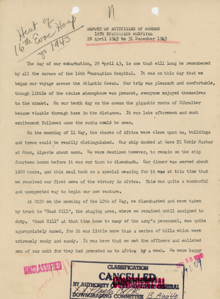
Nursing Report 16th Evacuation Hospital April to Dec 1943 – Describes crossing the Atlantic to North Africa and then heading to Italy on the HMHS Newfoundland, which was hit by a bomb and sunk. Eventually, they arrived and set up hospital services.
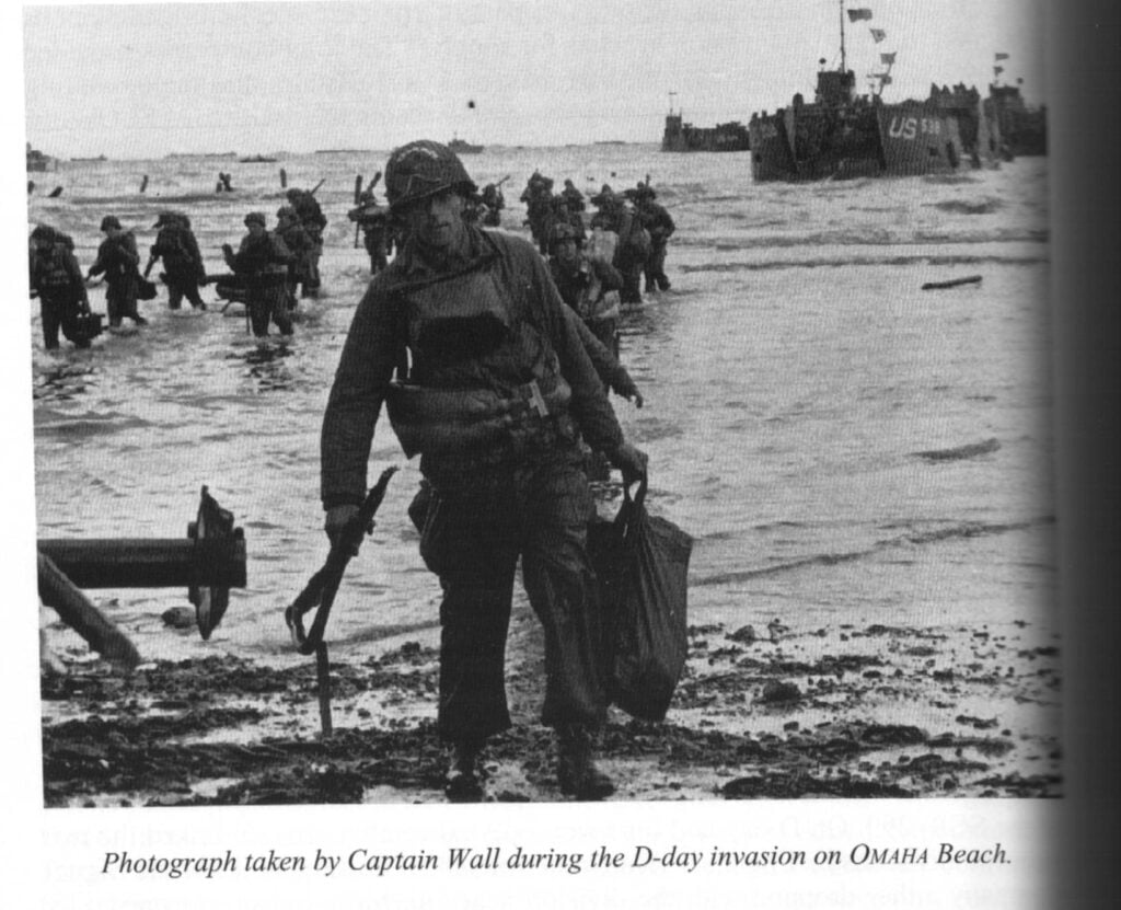
The D-Day landing narrative is a pretty good read of what it must have been like.
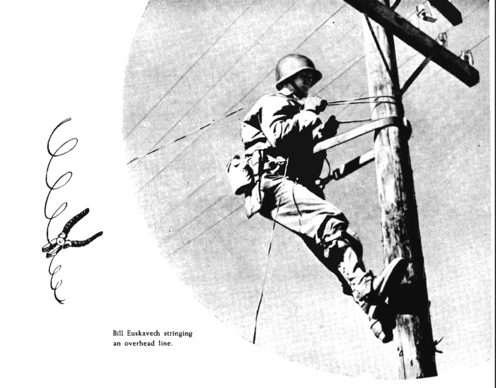
33 Months with the 100th Signal Company of the 100th Infantry Division 1945 – A Narrative of the Signal Company’s involvement. Discusses Construction and how each crew was assigned specific regiments to connect the wire to, along with having to repair and replace wire as it was cut or damaged. As well as the Radio section, the “T&T” or telegraph and teletype section, the message center section, the administration section (where presumably the mail clerk worked), the Signal Operations Instructions (SOI) section (which does training and checking of signal installations), Signal Supply section, Repair and Maintenance section, the Motor Pool (responsible for vehicle management and maintenance), the Mess section (responsible for feeding) and the Medical section.
Includes descriptions of training at Fort Jackson and sports and physical fitness testing.
Also makes mention of Tech 5th Chauncey N. Maggiacomo being asked to improve the Reel Unit RL-26, which he did. The old way required lots of manual labor to reel in the wire, ensuring it didn’t snag. The new method, instead of reeling it in from the back (like a winch), picked the wire up and fed it over a boom on the front of the truck.
Signal Corps Lineage and HERALDIC data and history – Information about the heraldic and lineage of different signal corps units. Shows the unit pin. By Rebecca Robbins Raines from the Center of Military History.
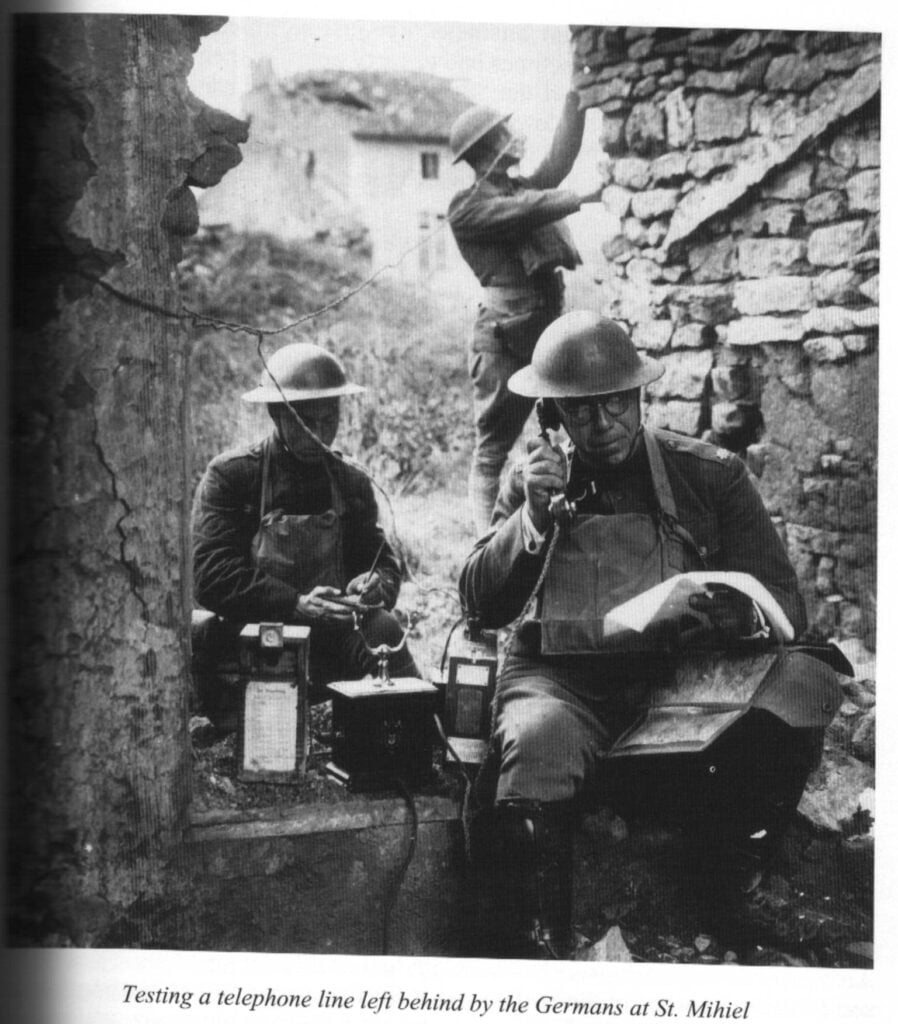
Signal Corps: The Emergency – History of the Signal Corps up till Pearl Harbor. By Dulaney Terrett from The Center of Military History
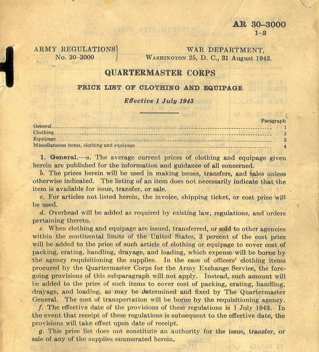
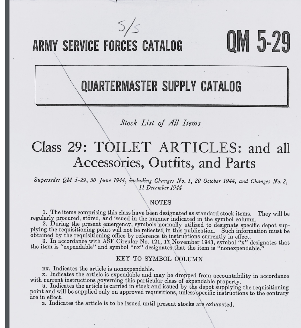
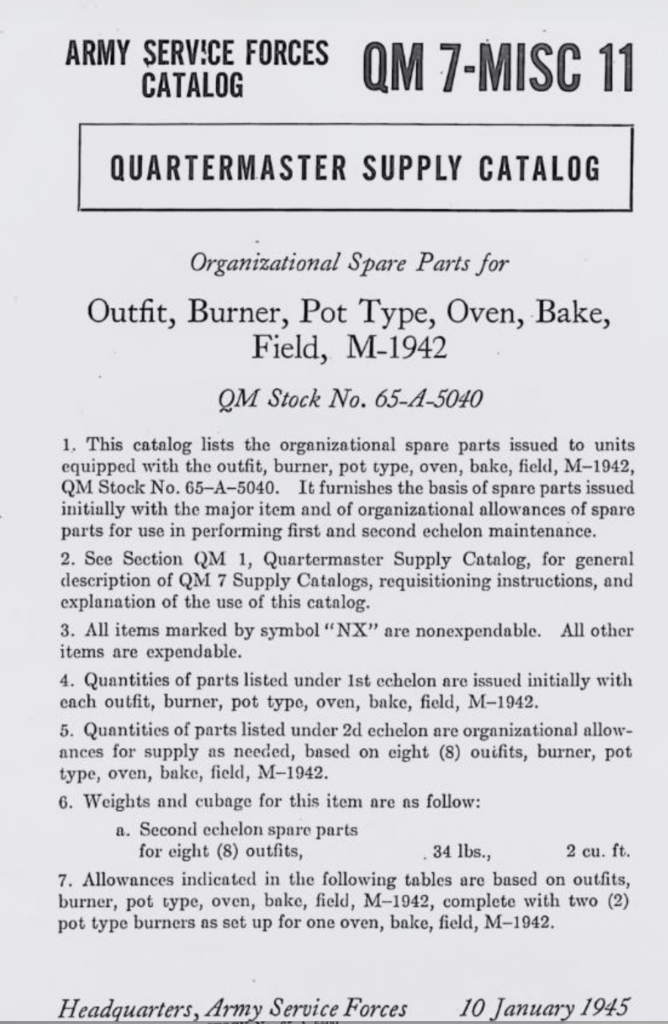
These are a historical narrative and go into detail on the account of the Corps’ actions. Mostly from a high-level overview. I’ll add more as I find them. If you’re interested in the Quartermaster supply catalogs, you can find them here.
For example, regarding camouflage bandages in the Pacific. We started manufacturing them in Sept 1943 as white bandages attracted snipers. By Nov 1943, 13 million dyed bandages were delivered. They came in an adhesive compress, 2-inch, 4-inch gauze bandages, compressed bandages, small and large first aid dressings, first aid packets, and triangular bandages. They were supplied either in field brown or in OD No. 7. (page 65)
The American Home Front: A Review by Tim O’Neill– A cultural review of the home front before the war and during. Includes political life, The Depression, travel, towns and cities, amusement, people, and trivia. I’m unsure of Tom’s credentials, but it seems to be a good intro primer.
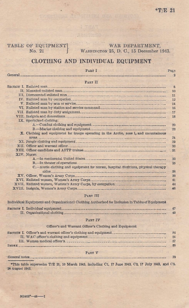
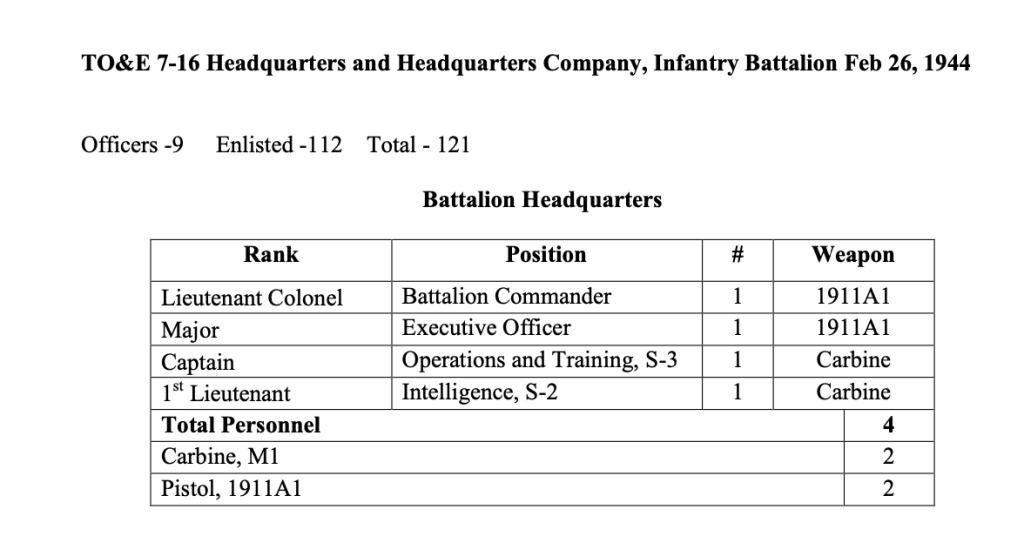
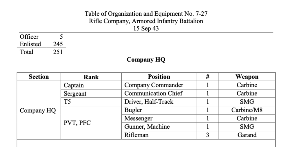
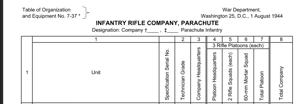
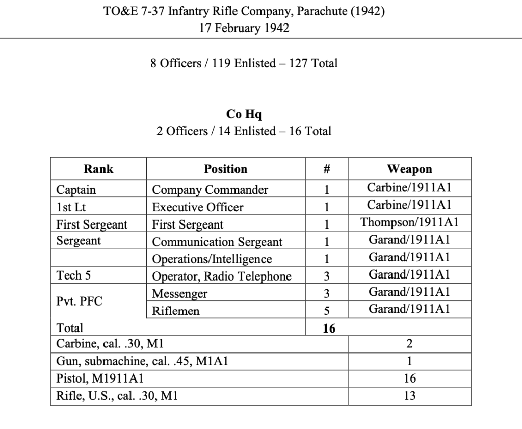
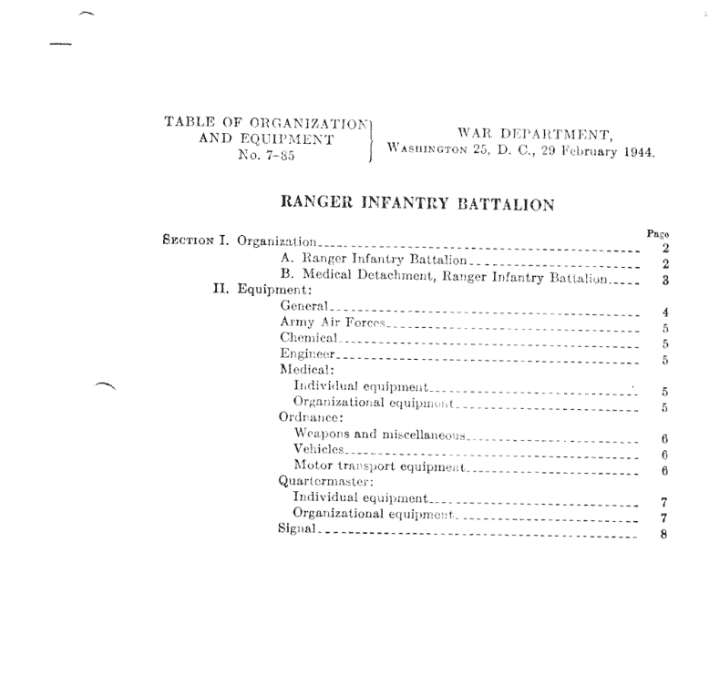
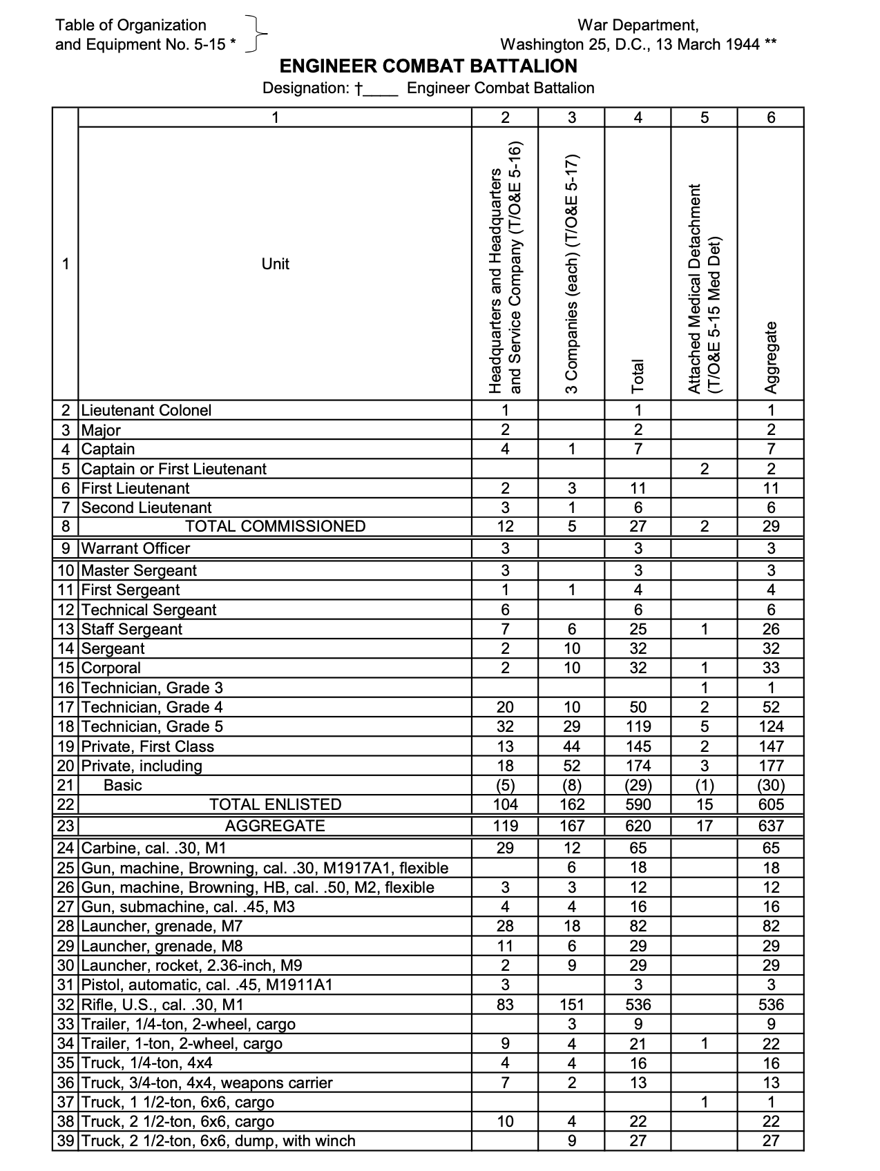
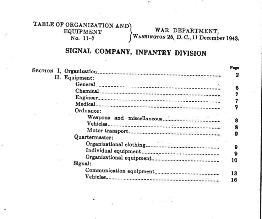
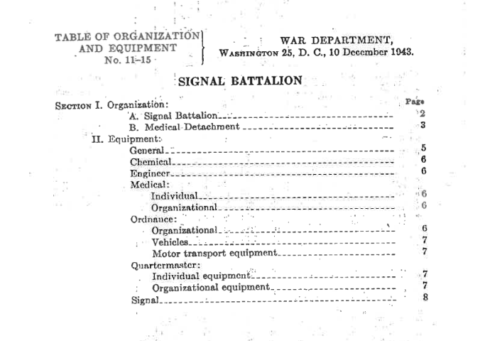
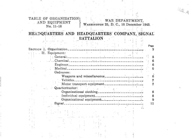
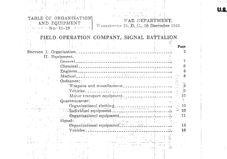
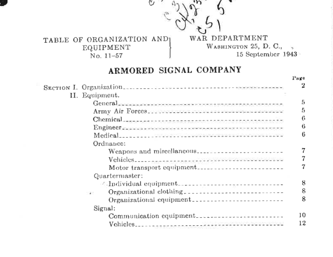
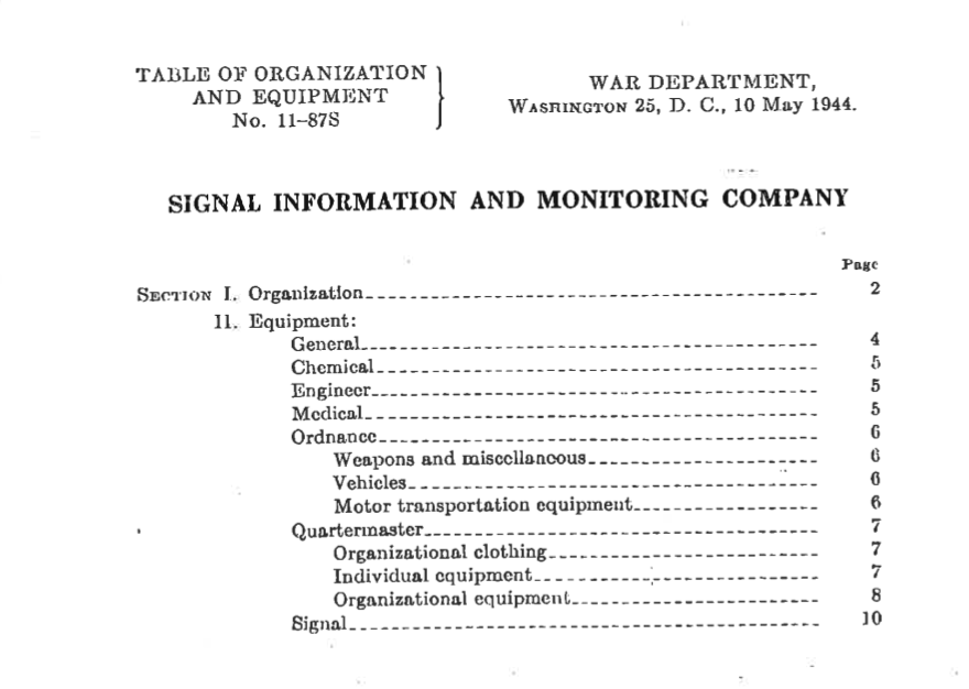
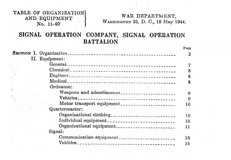
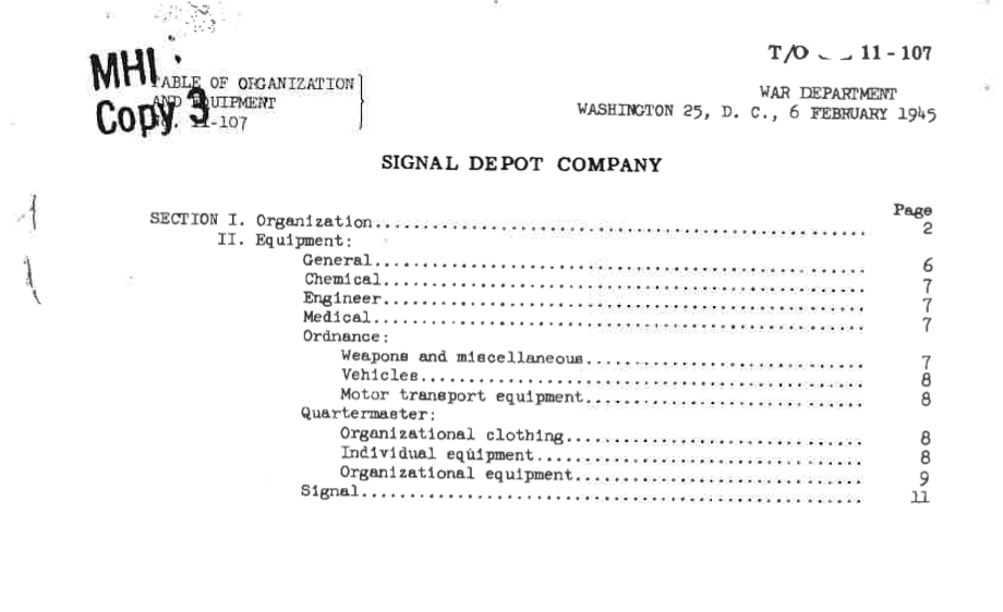
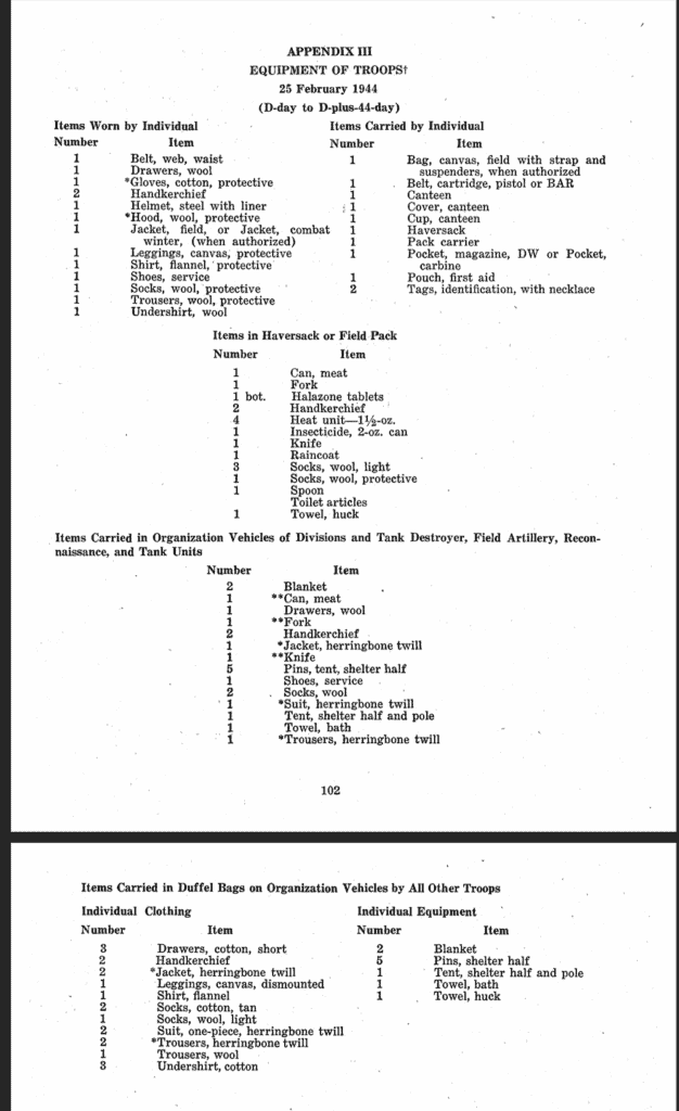
Below are some Tables of organization and Equipment that outline the personnel, equipment, and organization of various types of units. For reenacting purposes, it’s doubtful you’ll ever have this all (and it’s doubtful in WW2 the units in question ever did), but it’s a general guideline on what to aim for.
TO&E 7-37 Infantry Rifle Company Parachute -17 Feb 1942. A Table of Organization and Equipment for what a rifle company should have in terms of manpower and items. This is a cleaned-up copy of the source material.
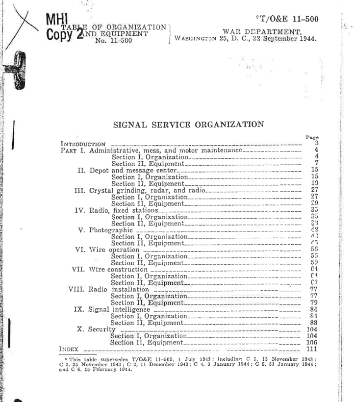
11-1027 Signal Detachment, Headquarters Ship 11-1050 Film Library Organization 11-1095 Army Signal Battalion, Special 11-1096 Headquarters and Headquarters Company, Army Signal Battalion, Special 11-1097 Wire Operation Company, Army Signal Battalion, Special 11-1098 Signal Construction Company, Army Signal Battalion, Special
TOE 11-147S Joint Assault Signal Company 12-30-1944 – For an after-action report of the 593rd Joint Assault Signal Company which landed at Leyte Island on Oct 20th 1944 as part of the 96th Infantry Division read: 593rd Joint Assault Signal Company. It goes into detail about the problems it faced as well as the nitty-gritty of how the company was supposed to operate.
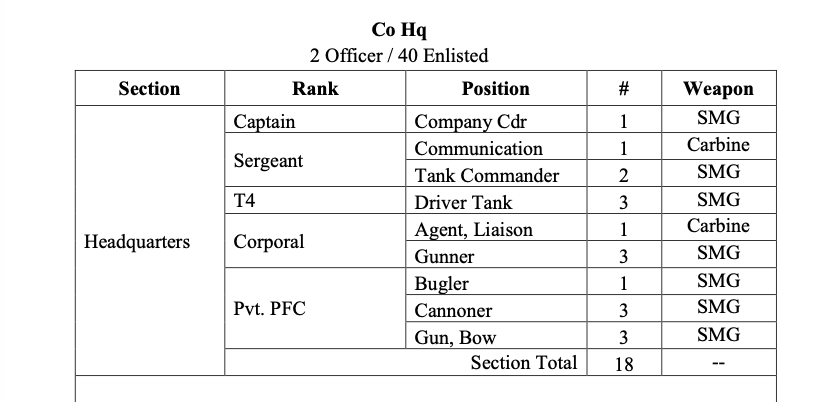
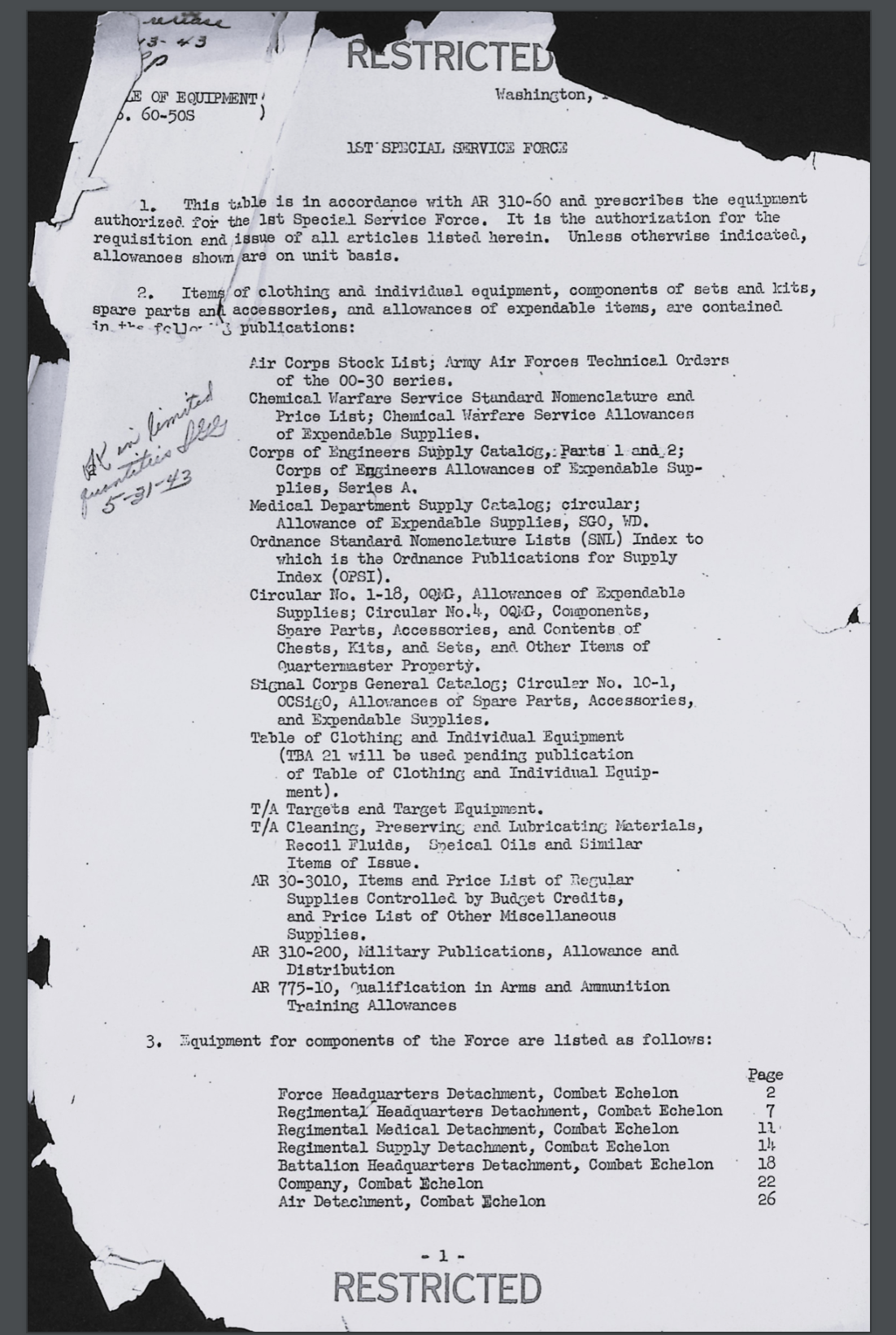
TE 60-50S 1st Special Service Force – Zip file of the entire Table of Equipment for the 1st Special Service Force. The zip file is kinda wonky, but I’m too lazy to fuck with it and merge PDFs at the moment.
This lists supply catalogs. Supply catalogs are books filled with descriptions and nomenclature of various items used by different branches.
Signal Corps and Radio and Telephone
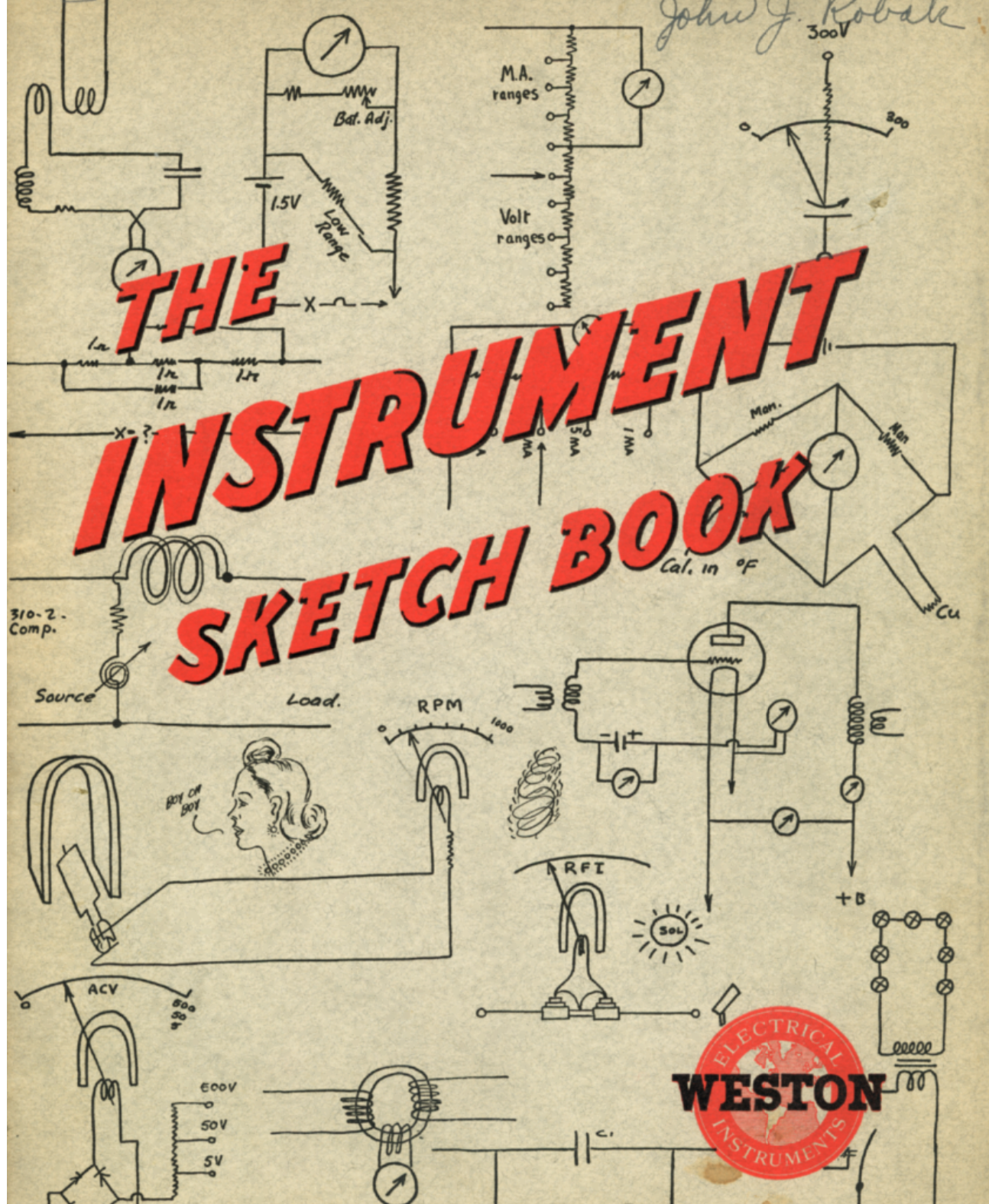
The instrument sketch book Weston Electrical Instruments 1941 – A sales book showing various products. Some of these civilian models may have ended up in Signal Corps hands. Also nice to have a reference guide in case you come across an obscure electrical item that you’re not sure about.
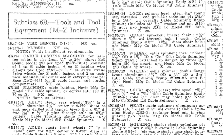
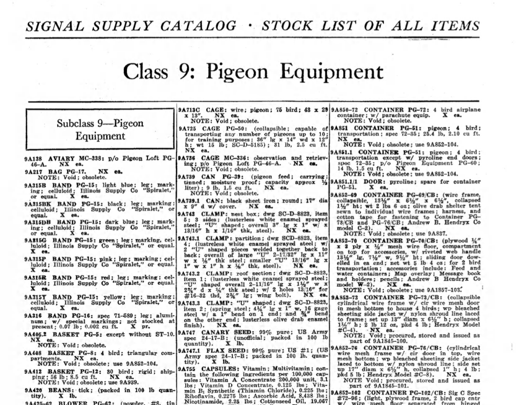
Signal Supply Catalog 1945- SubClass 6r M-Z Tools, Pigeons Class 9, Meteorological Class 7 – A partial listing of the whole Signal Corps Supply Catalog. Consisting of the total stock numbers and nomenclature of all items available to the Signal Corps.
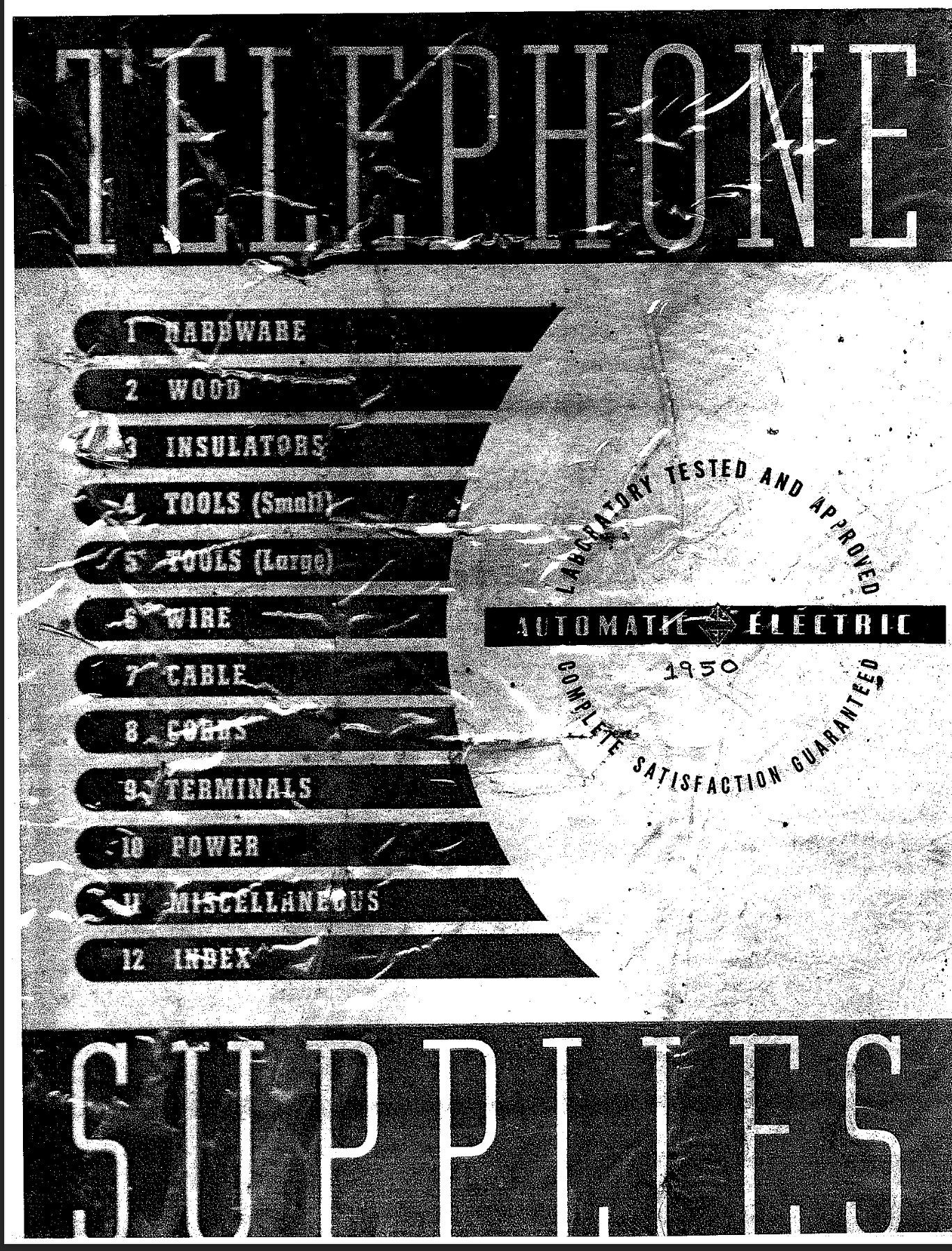
Automatic Electric Telephone Supplies 1950 –Part One and Part Two. A product sales book showing telephone supplies available in 1950. Good for cross-referencing items. Includes hardware, wood, insulators, tools, wire, cable, cords, terminals, power, and miscellaneous items.
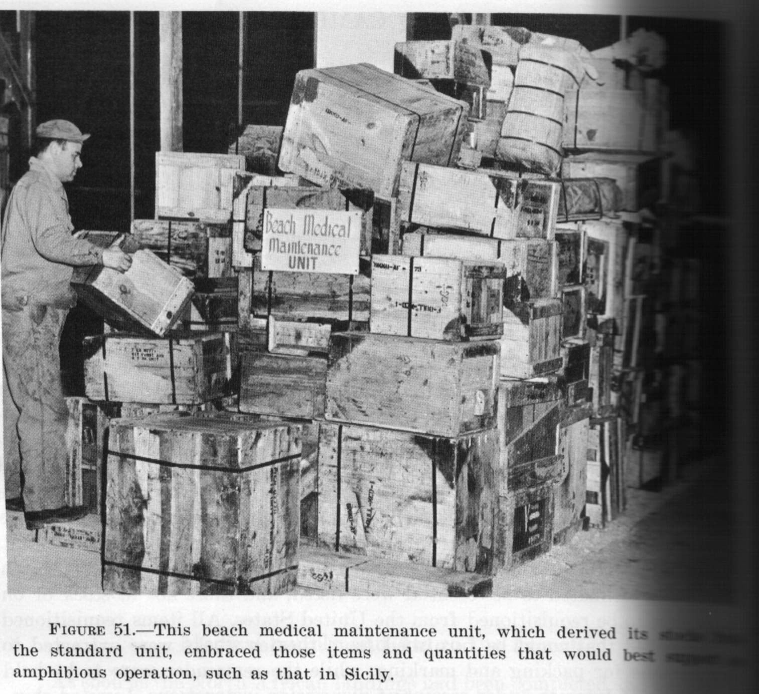
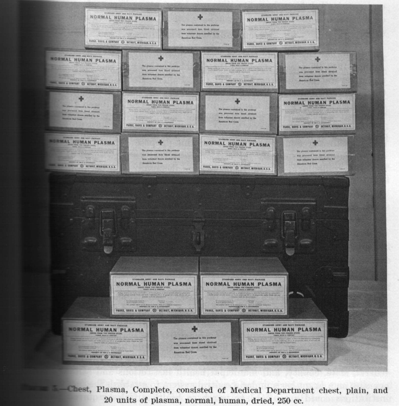
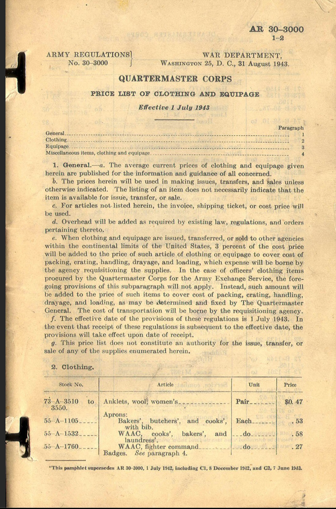
Medical Supply Catalog Med1 to Med3 March 1944 – This is the medical department’s complete catalog of available products. It lists items available, the associated stock number, as well as the price. It also includes pictures of some of the times. It’s a beefy PDF file that you download from my Google Drive. The Med-dept.com contains a wealth of information that goes into more detail on some of the items in the catalog, such as individual first aid packs.
Medical Department Supply Catalog 1942 – This is the medical department’s complete catalog of available products. It lists items available, the associated stock number, as well as the price. It’s a beefy PDF file that you download from my Google Drive. The Med-dept.com contains a wealth of information that goes into more detail on some of the items in the catalog, such as individual first aid packs.
Medical Department Supply Catalog June 1st, 1943 – A list of items available for the medical department, including costs and supply class. Also includes a section on organizational equipment, medical department assemblages and component parts, and the cost of medical department blank forms.
Quartermaster Corps Manual QMC 14-2: Use and Care of Office Equipment and Supplies – Dated Feb 1945. Written in response to the drastic reduction of office supplies, and describes how to use and care for office supplies to make them last longer. Contains nuggets of information like “use both sides of the paper” and “to re-use file folders, flip them inside out”. Also mentions reusing rubber bands as rubber was a wartime ration good. It also has a good section on how to care for typewriters, which, if you don’t know where to begin, is a good place to start! Print on ivory regular paper, 8.5″ x 11″
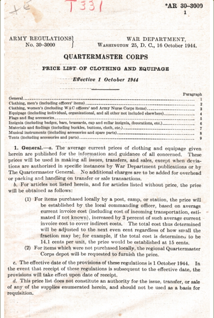
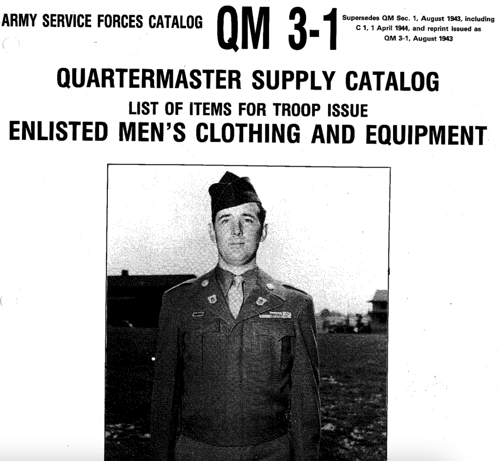
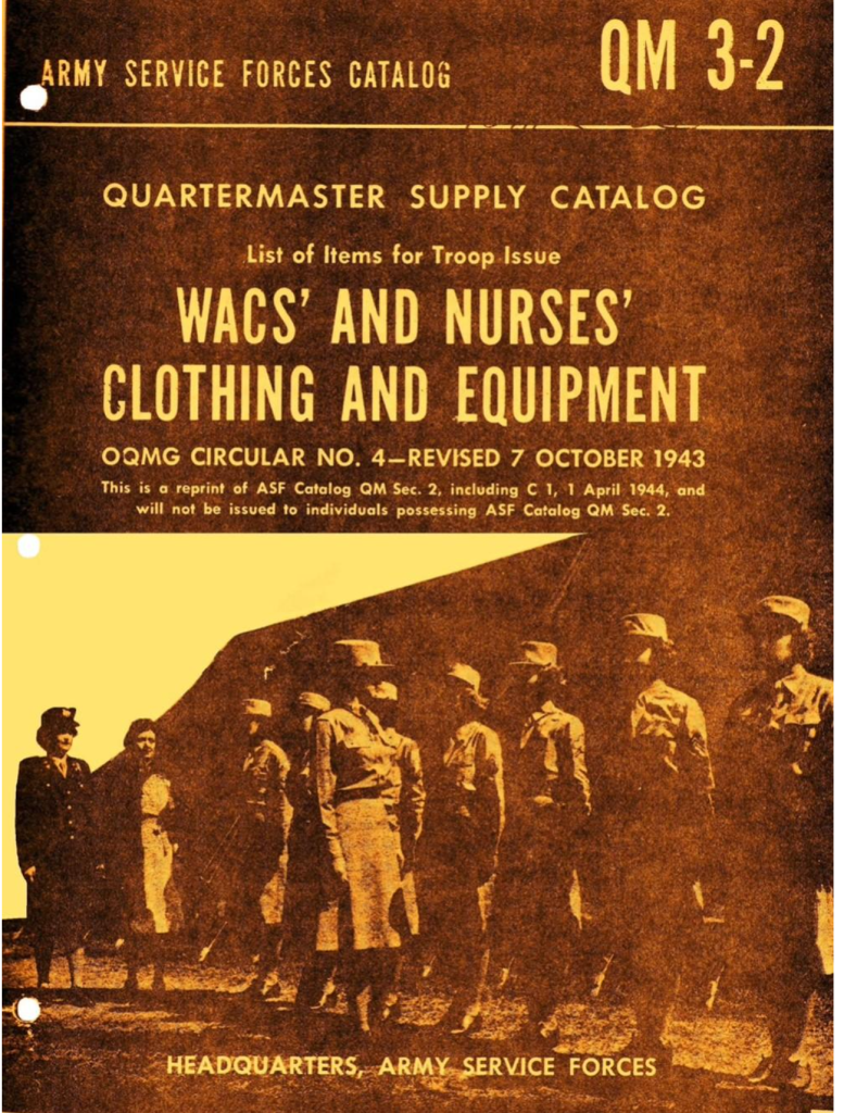
Quartermaster Supply Catalog QM 3-1 1946: List of Items for Troop Issue Enlisted Men’s Clothing and Equipment. This catalog was made in May 1946. Lists out all the things available to troops at the end of WW2. Supercedes QM1.
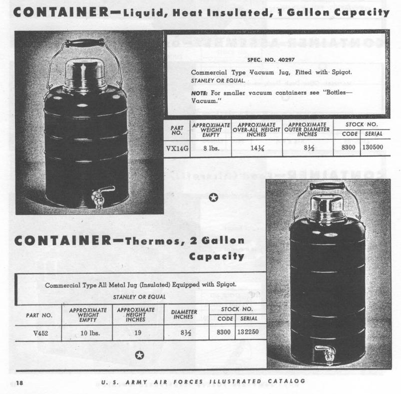
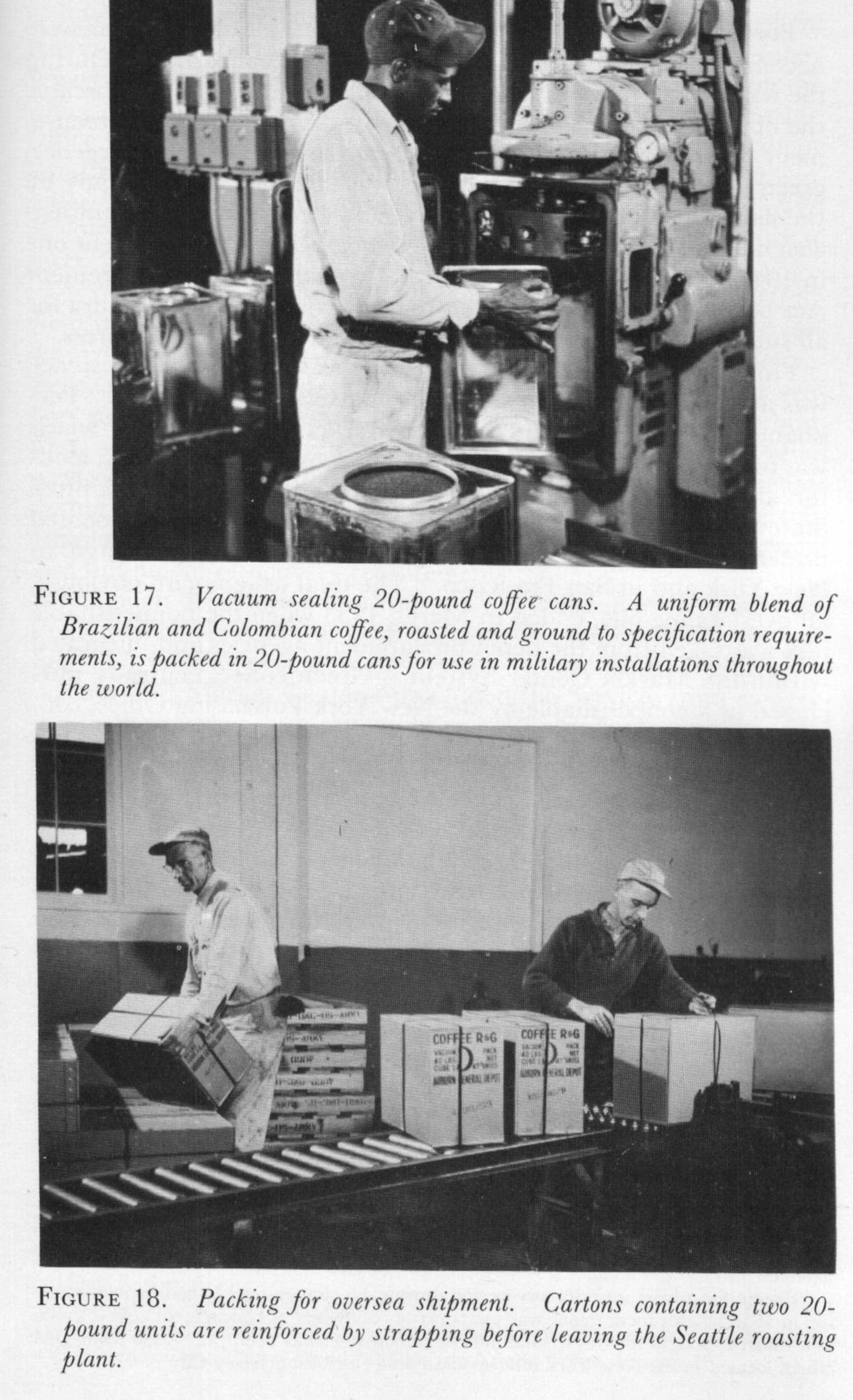
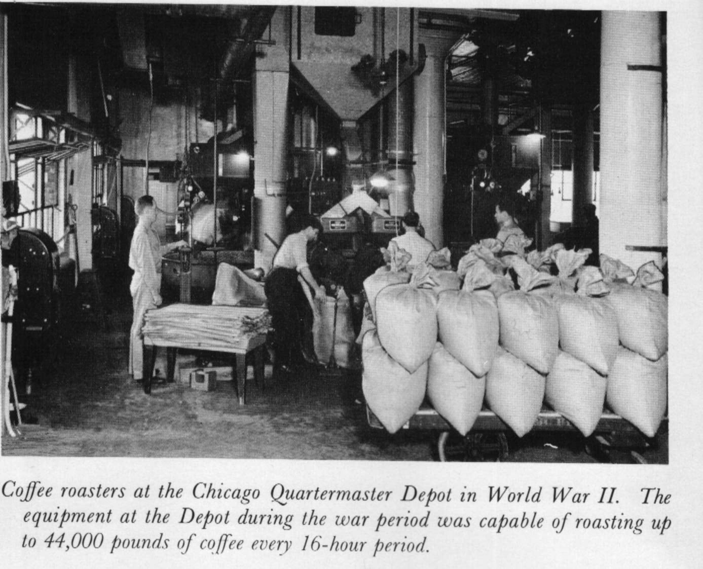
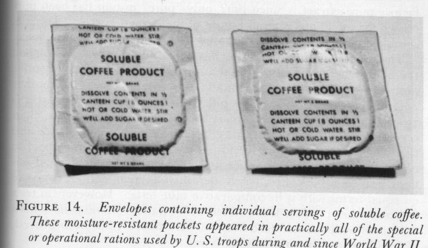
US Army Air Force Illustrated Catalog – I have a single scan showing two types of Coffee Containers, a 1-gallon and a 2-gallon. These could be made from Stanley or another firm. I’m unsure what catalog number and date it came from, as there appears to be no free version of it.
For the moment, I’ve added a few images to this block of coffee taken from: Coffee For the Armed Forces: Military Development and Conversion to Industry Supply By Franz A. Koehler; QMC Historical Studies Series II, No. 5 Historical Branch, Office of the Quartermaster General: Washington D.C., 1958.
Maybe I’ll eventually expand it out to a full post.
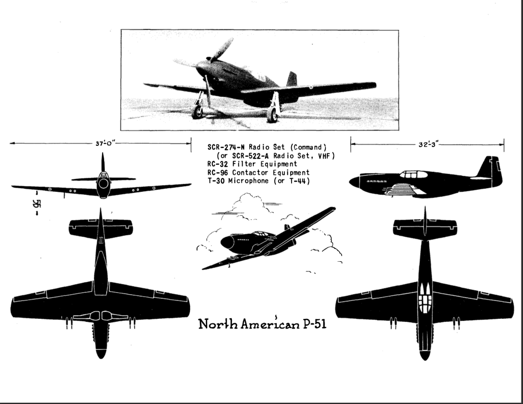
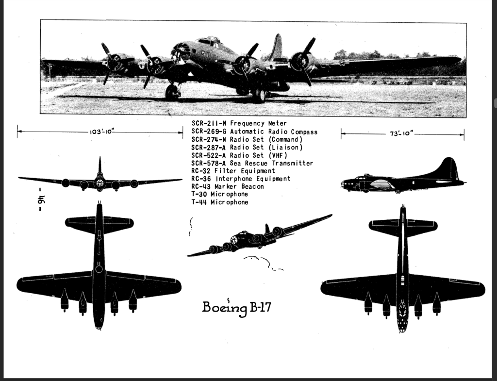
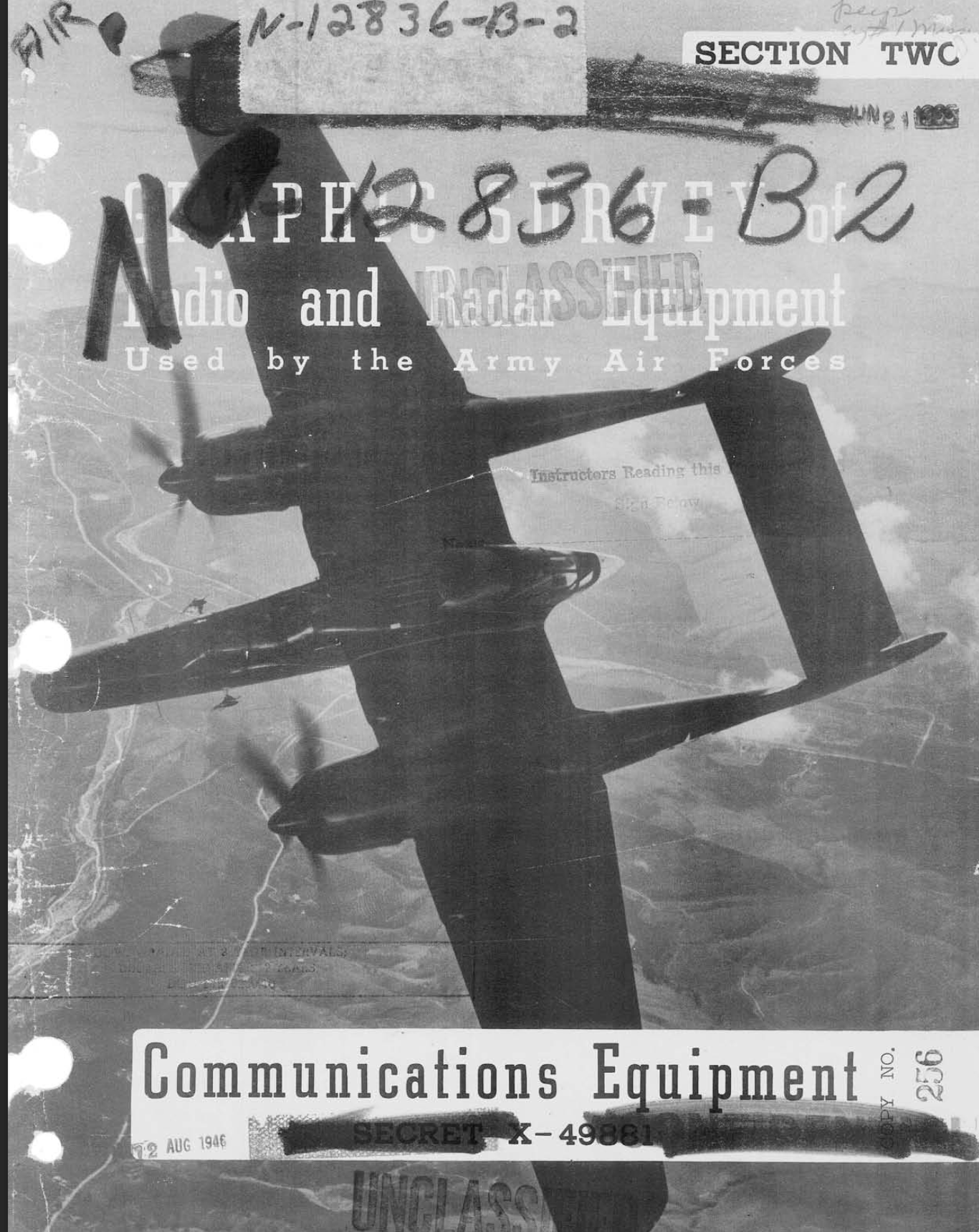
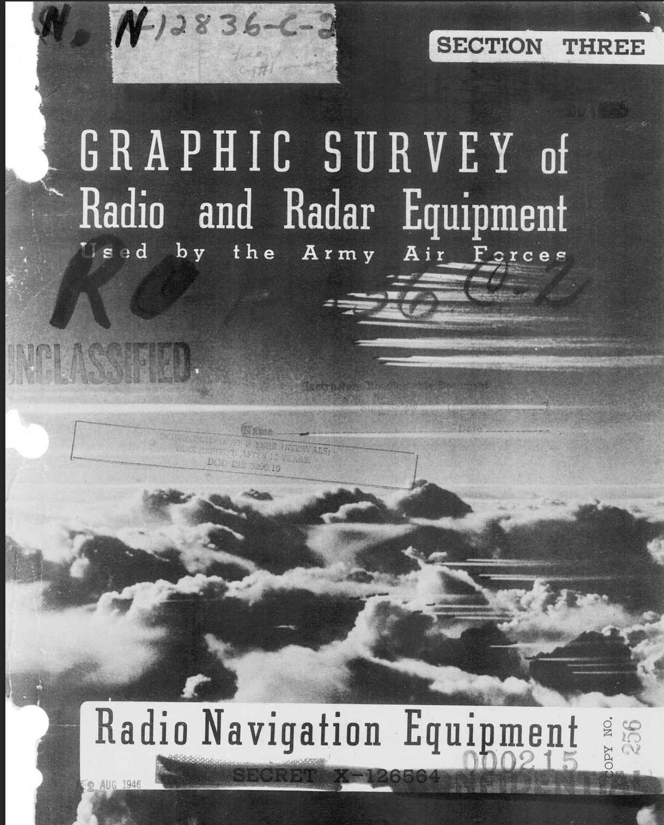
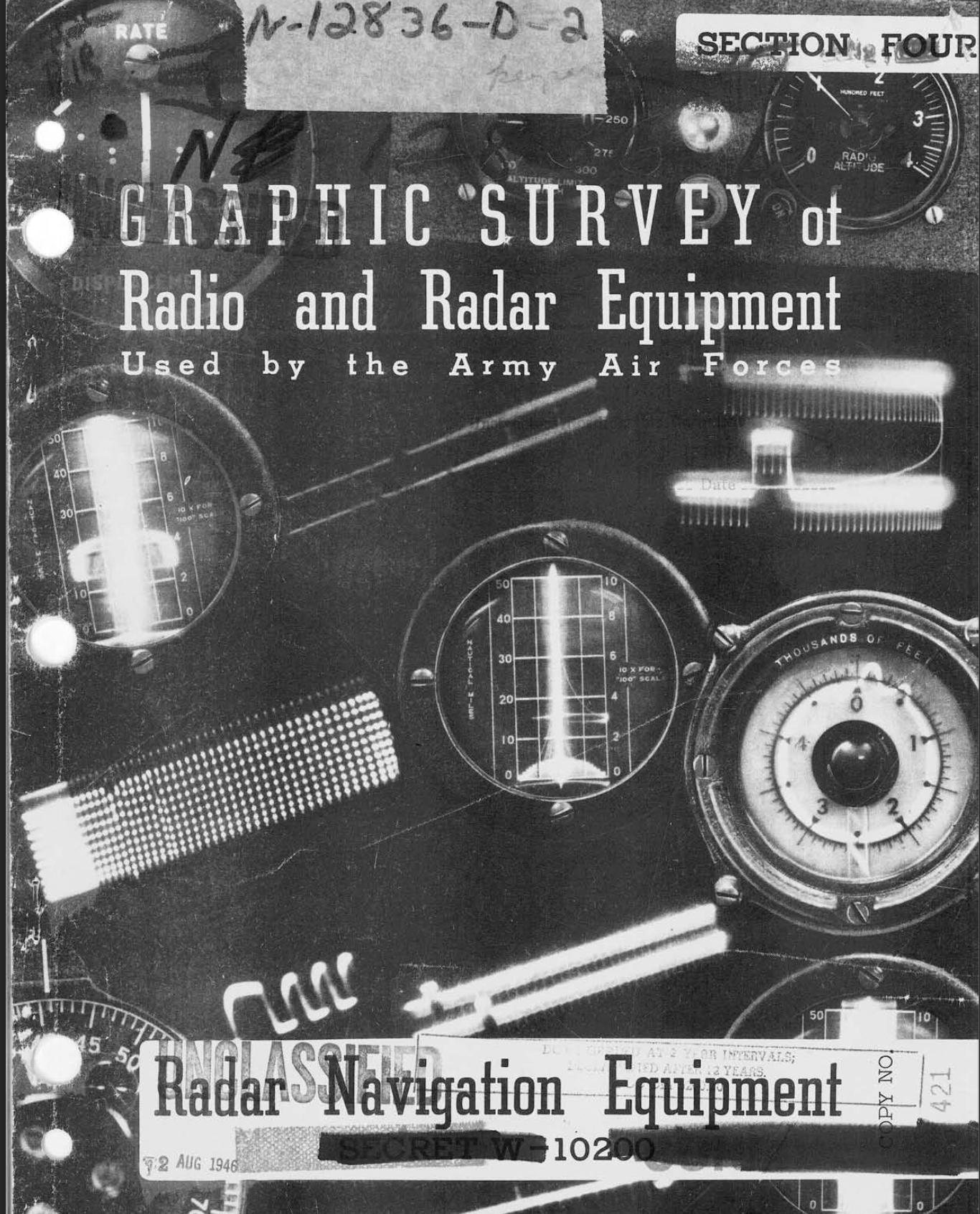
Graphic Survey of Army Air Forces Radio Equipment – Consists of four sections conducted in 1945.