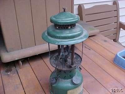
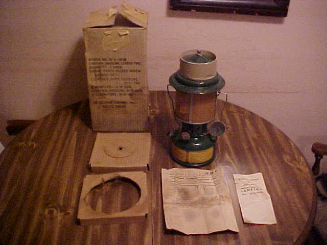
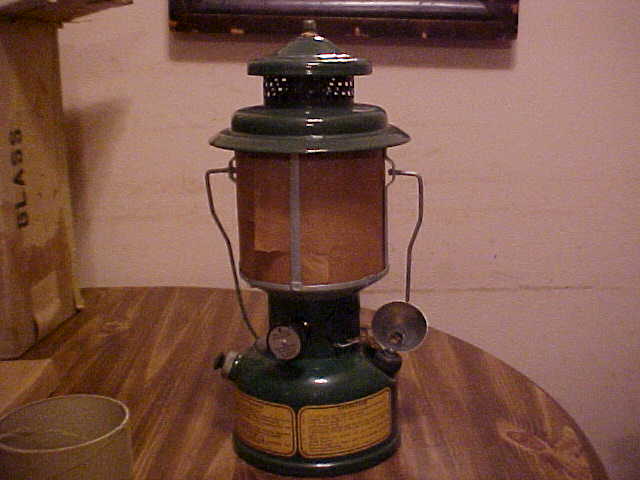
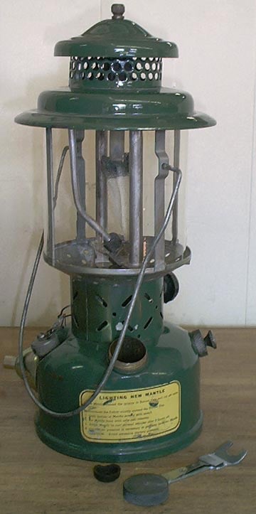
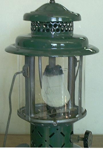
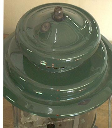
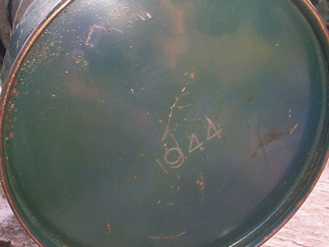
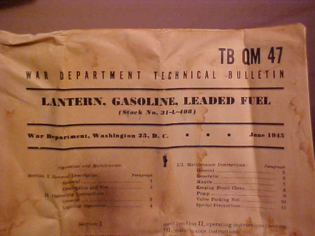
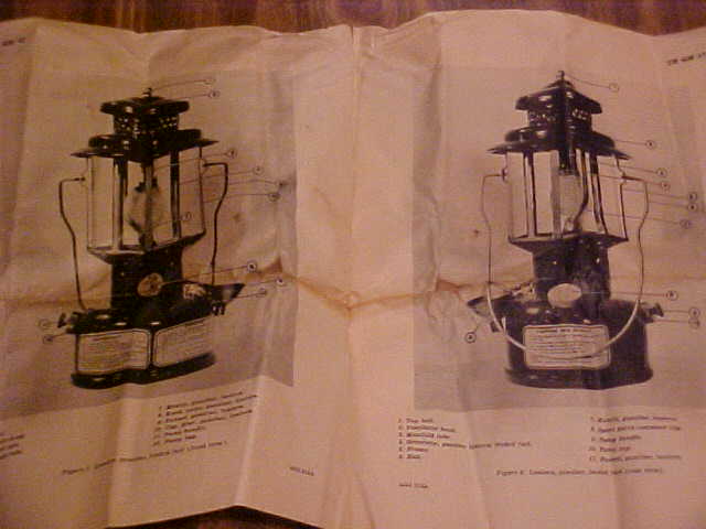
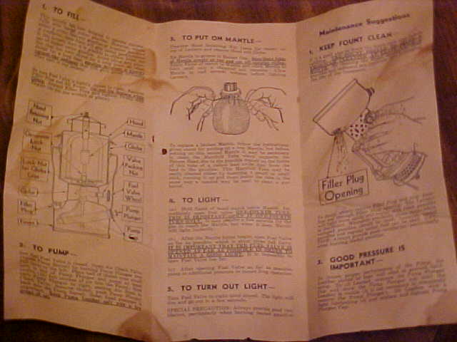
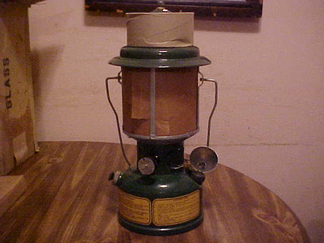
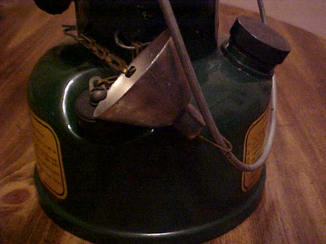
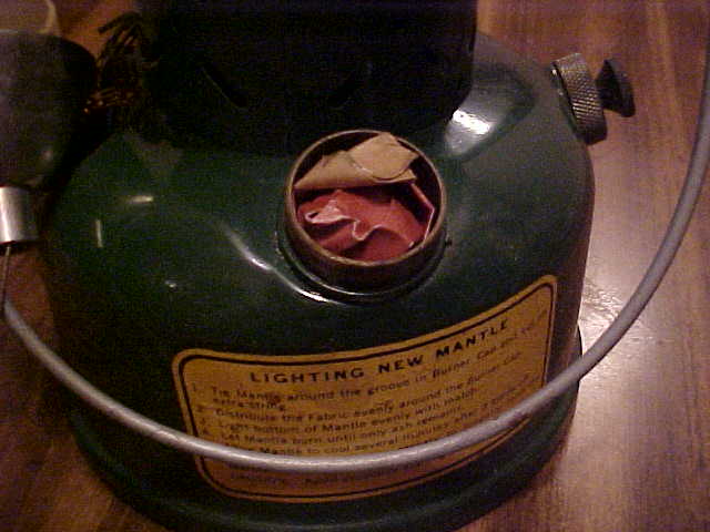
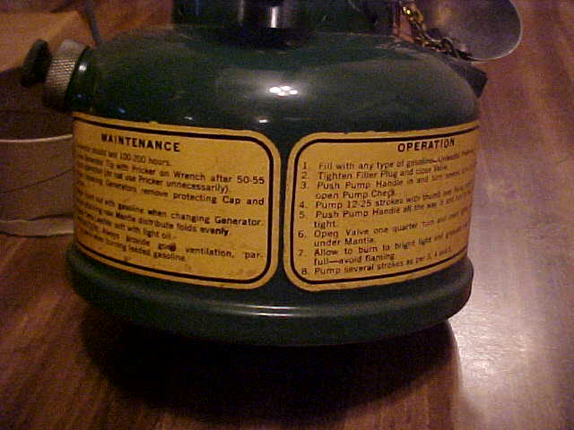
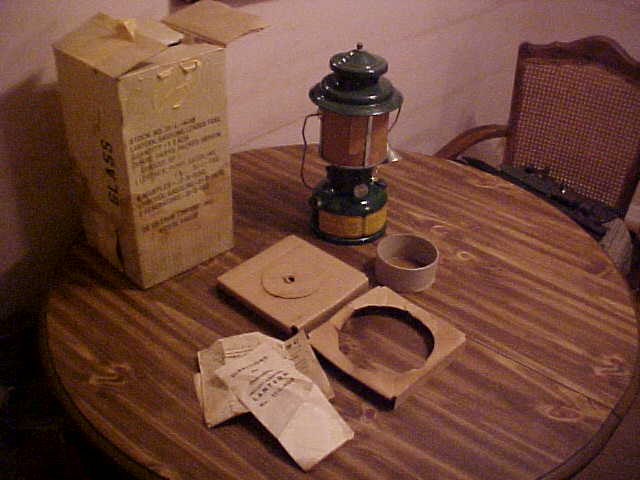
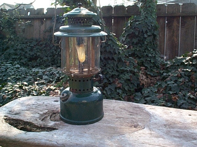
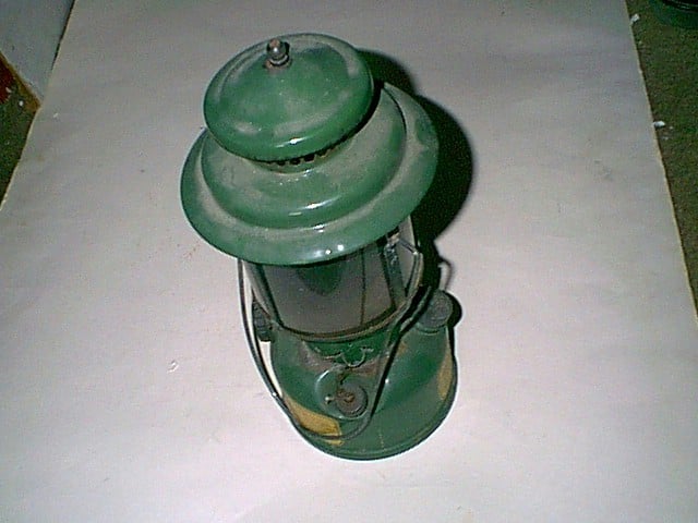
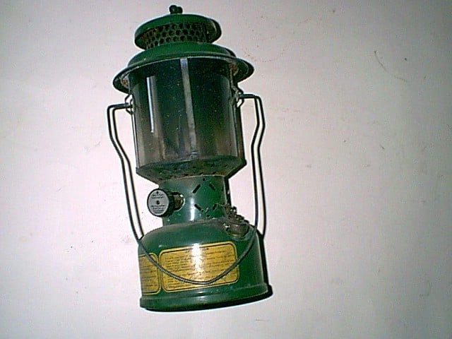
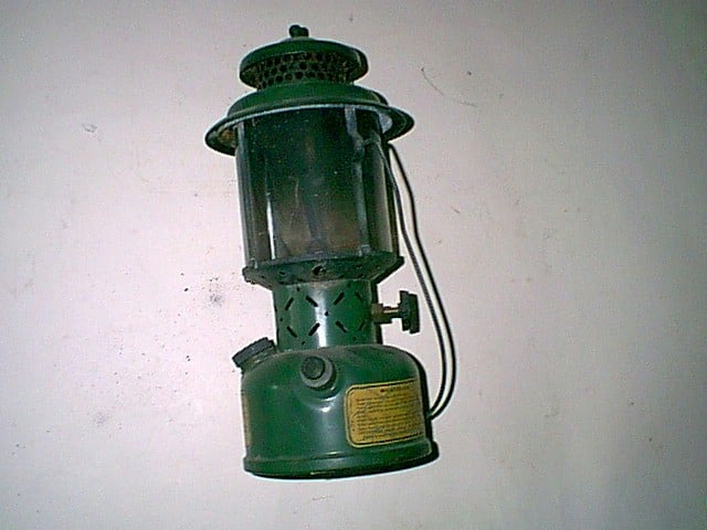
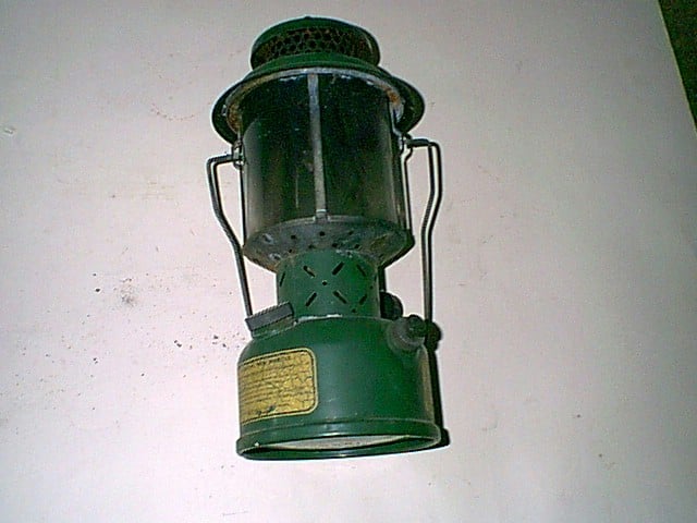
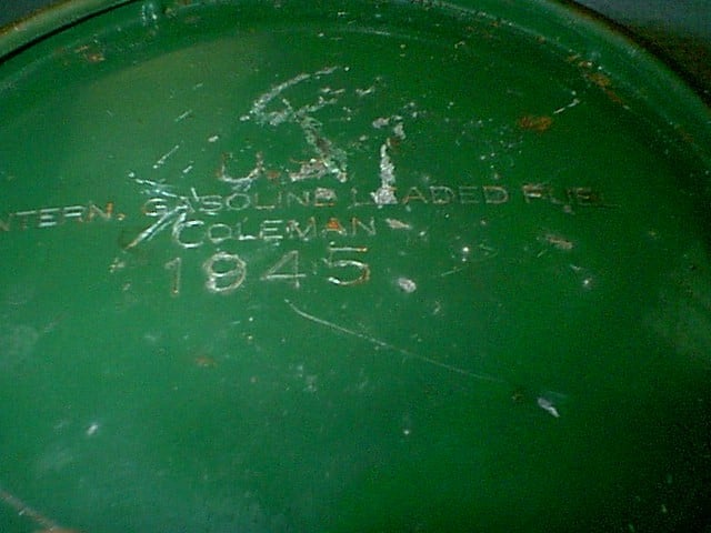
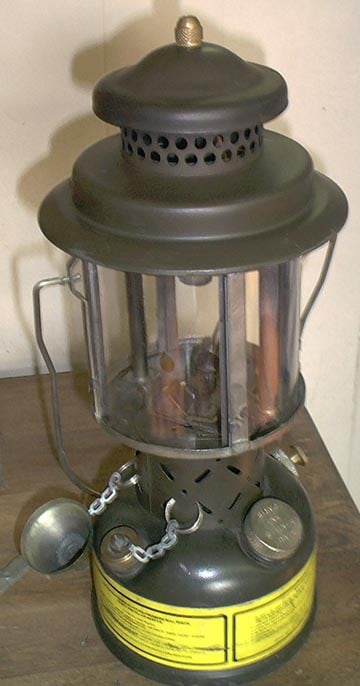
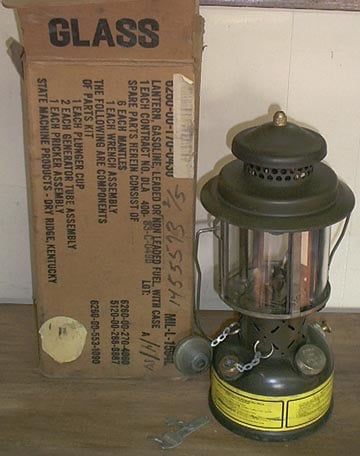
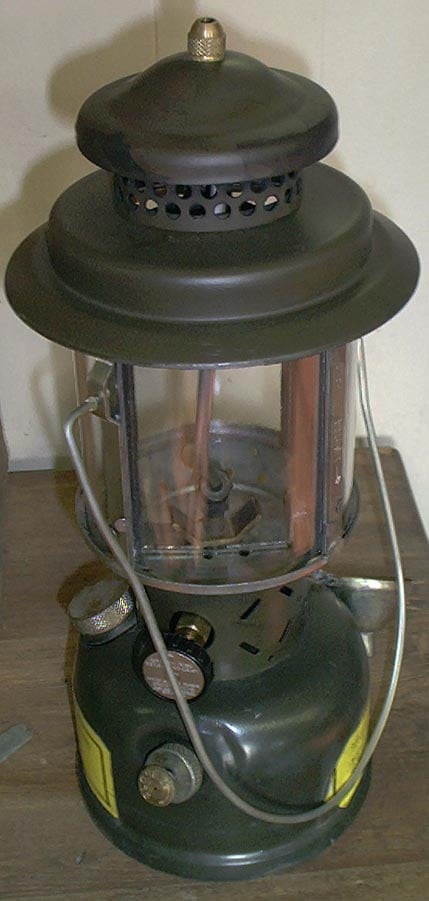
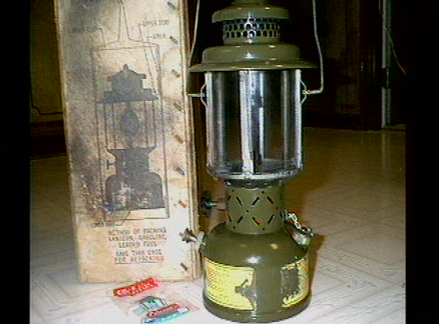
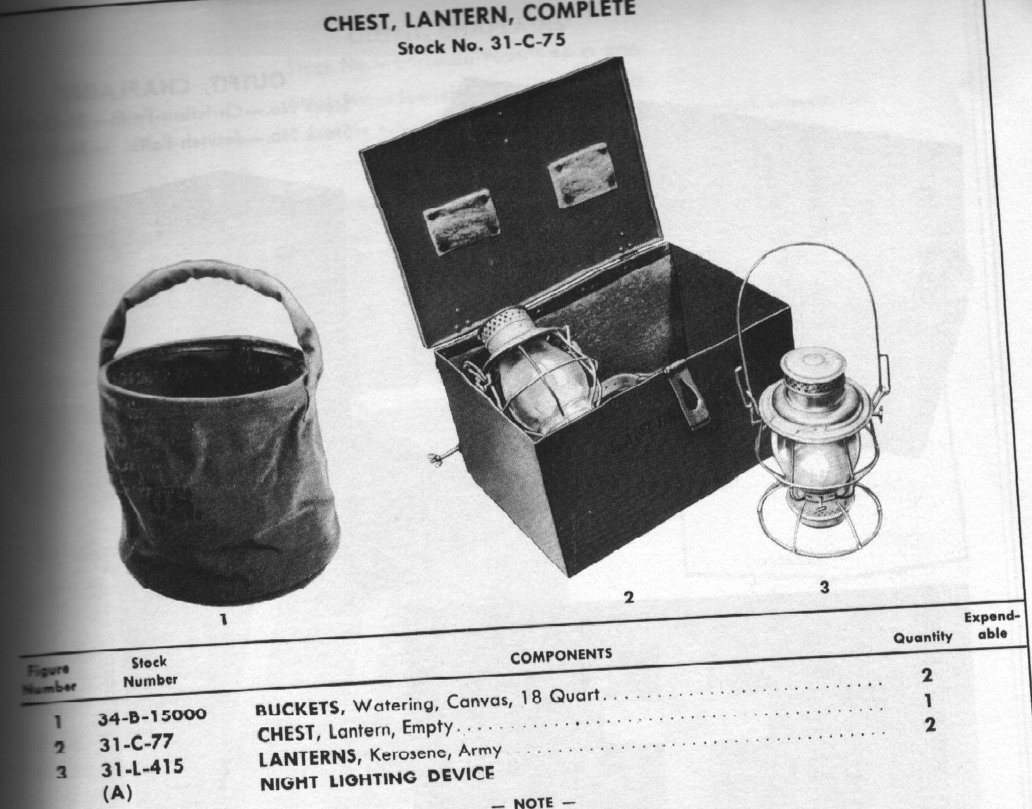
US Army Lanterns in World War Two were produced by Coleman (and probably others) and came in a green color. The images below show a few examples of it, including an unissued one in the original packing material –
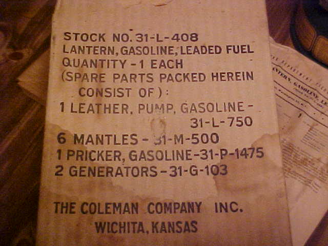
There is also a Lantern Gasoline Leaded Fuel, QM 8-Misc 1 quartermaster supply catalog dated Jan 1945 that outlines the spare parts for the unit.
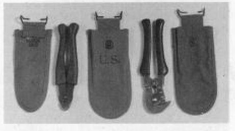
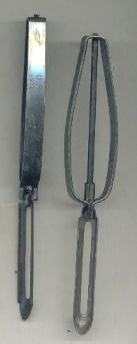
Shown on the left is a pair of Model 1910 wire cutters with a pouch dated 1918. The metal jaws are marked “U.S.”, and “5000-V” is molded into the rubber handle. These cutters were dual-purpose tools, featuring a wire-cutting slot as well as serrated jaws that allowed them to be used as pliers.
On the right is a pair of M-1938 wire cutters, stamped “U.S., HKP, 1944.” Unlike the Model 1910 cutters, the M-1938 functioned solely as wire cutters. Accompanying them are two pouches: a light olive drab pouch dated 1942 on the left and a dark olive drab pouch dated 1944 on the right.
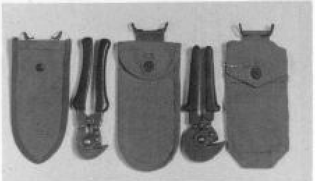
Shown on the left is an undated USM pouch designed for the standard M-1938 wire cutters, used during the early years of World War II.
The cutters on the far right are stamped “USMC 1944.” The purpose of their enlarged head is uncertain, though it may have been intended to provide additional strength. The cutting blade is sharpened along only half of its length, with the remaining portion being serrated.
The pouch to the left of these cutters is dated 1944, while the pouch on the right is British-manufactured and dated 1945
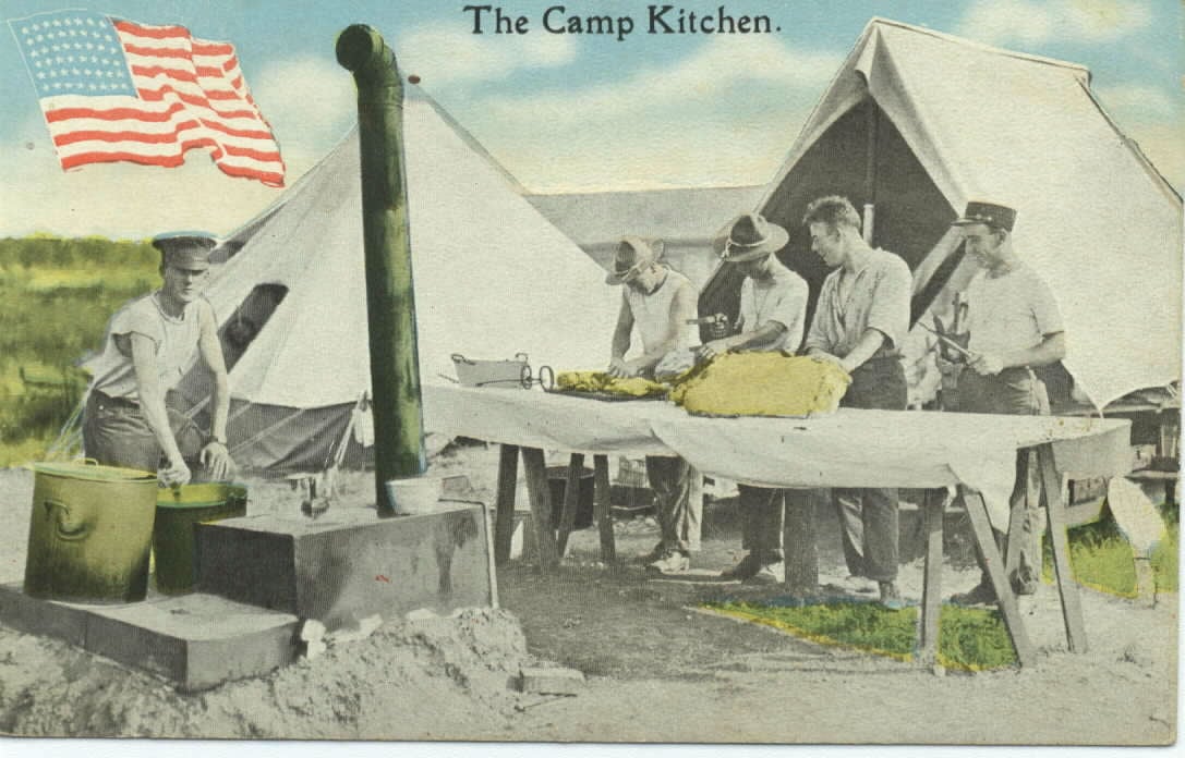
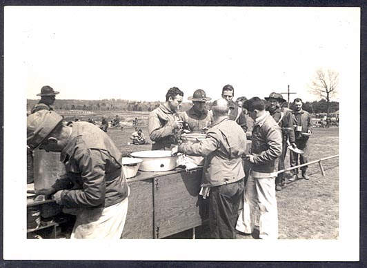
Camp Kitchen Postcard – I don’t have a date on this, but it looks like maybe 1920s-1930s, and they’re cutting up part of an animal.
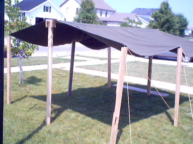
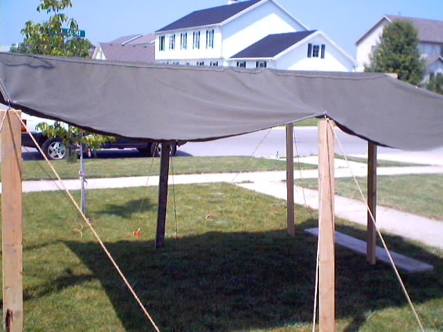
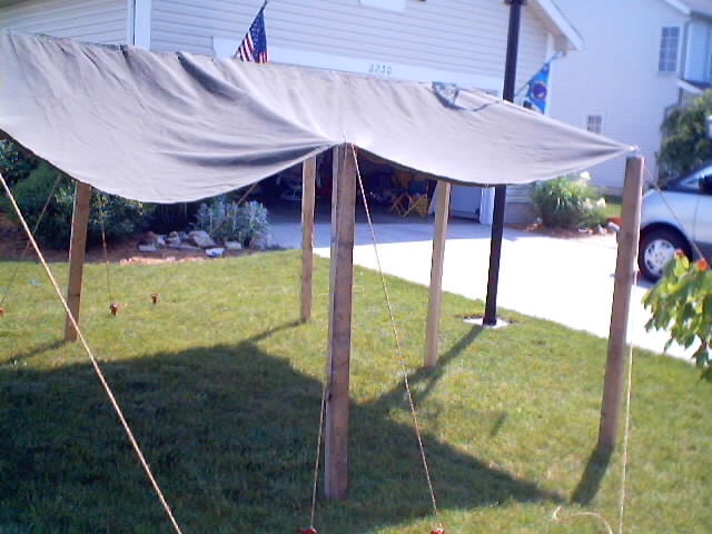
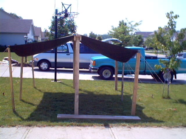
Mess Tent – This is a fantasy piece I cobbled together after drawing inspiration from period photos. I purchased a large olive drab canvas tarp that had grommets all around it. I think the grommets were brass, and I may have painted them black (though I’m unsure if that’s even period correct).
I bought some 2x4x6 or 2x4x8 (I don’t recall the height) and created the poles. Or maybe I bought eight 2x4x8s and cut six of them down to be 6 feet high to act as the edge poles, and two to be 8 feet high to act as supports for the ridge pole.
I then drilled a small hole in the center of each edge pole and screwed in an eyelet, which then went through the grommets. I used Manila rope and two stakes per pole to secure it to the ground. The stakes were the Vietnam era orange ones, but for WW2, they should’ve been large wooden circus-type stakes.
Now, the ridge pole itself, I’m unclear how I made it. If I were to make it today, I’d probably figure out a way to lag bolt the ridgepole to the 2x4x8 pole. I’d also make the ridge pole collapsible. If I were using 2x4s as the ridge pole, I’d cut the pole in half and use lag bolts to attach adjoining pieces of wood to each half.
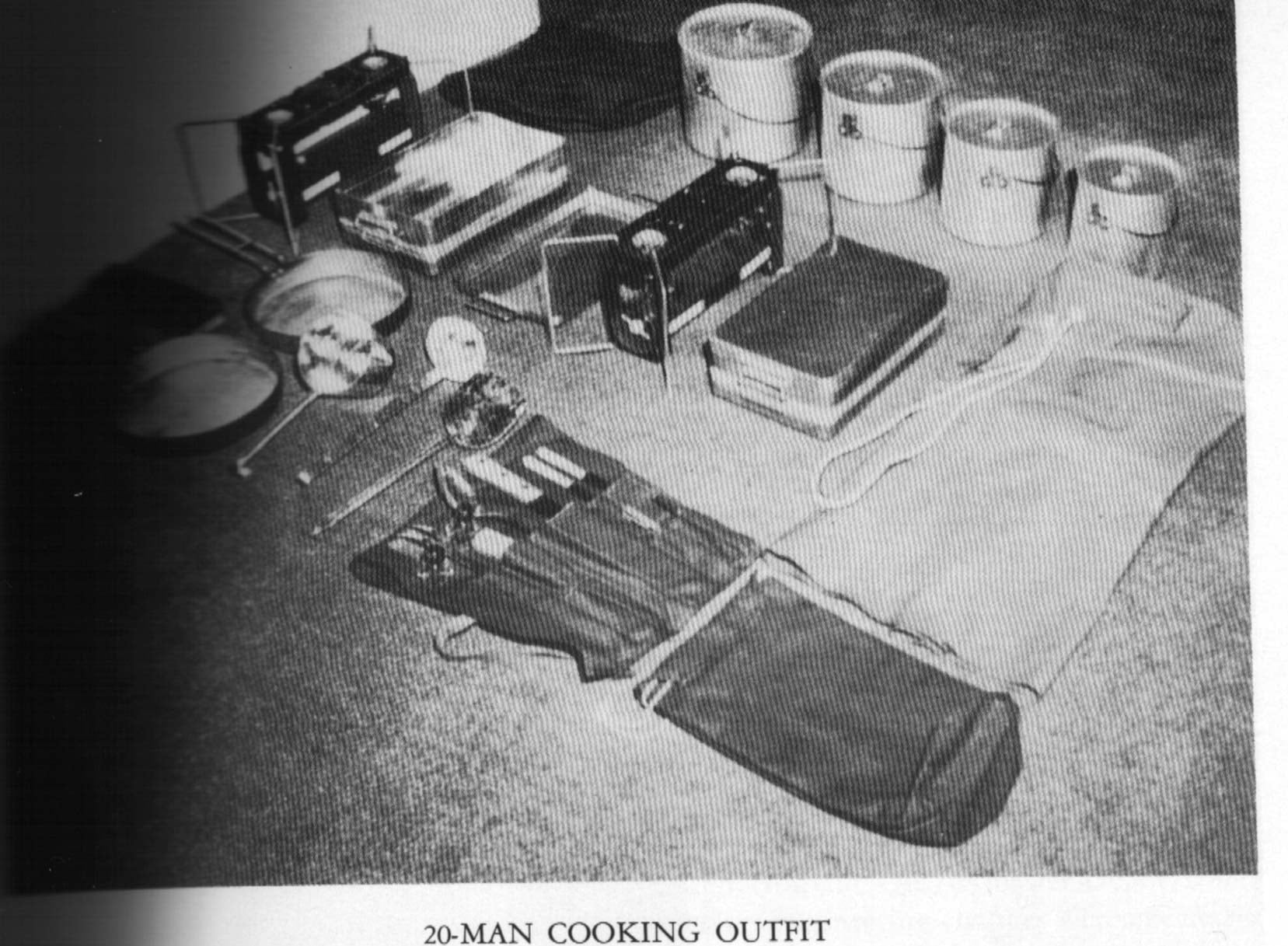
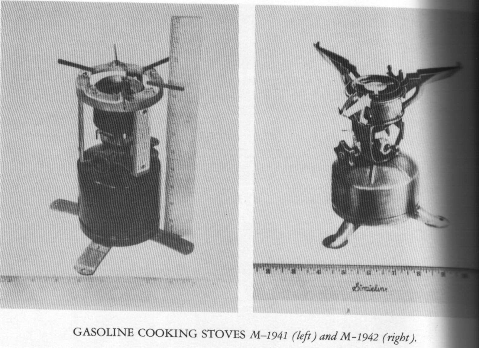
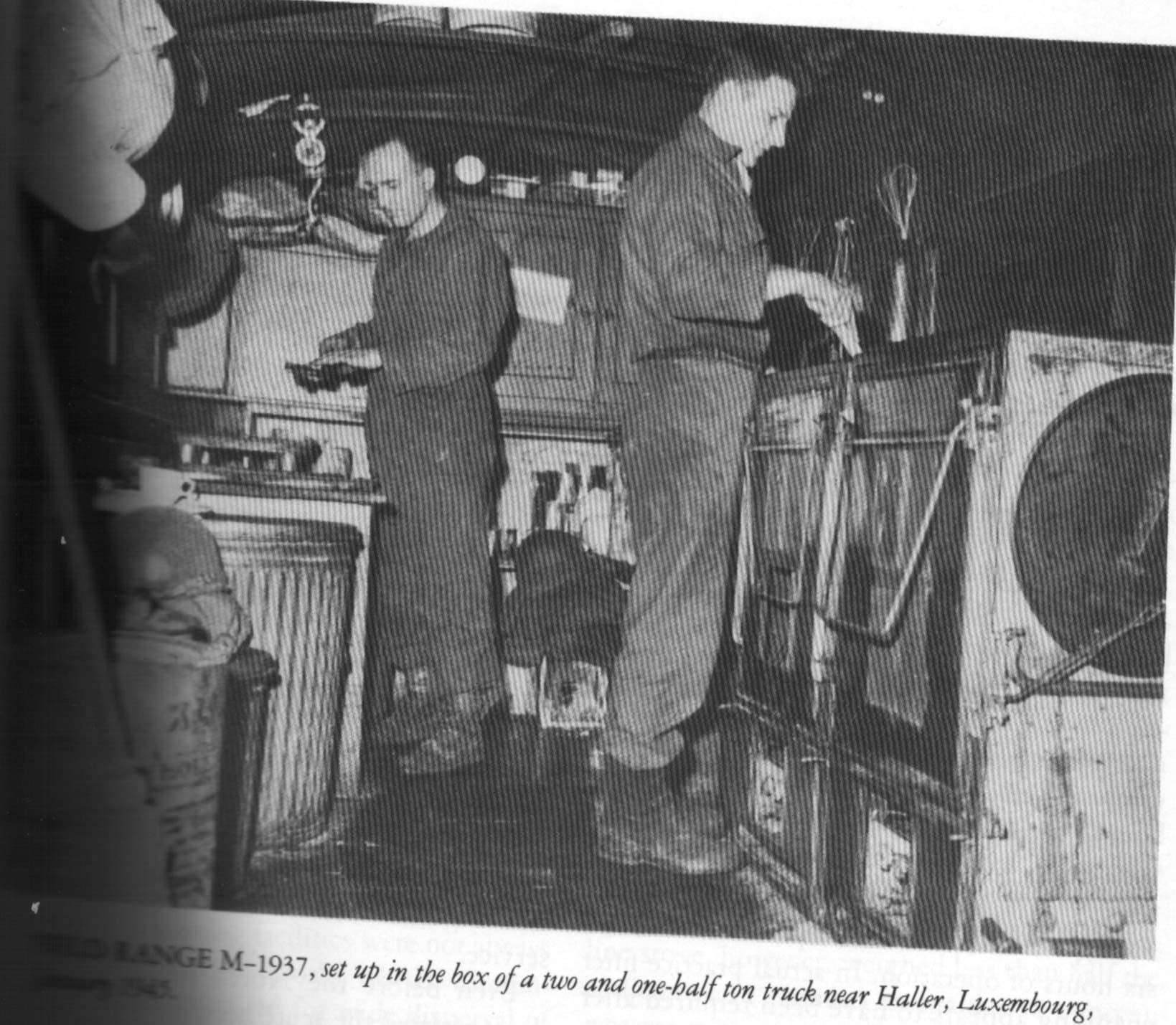
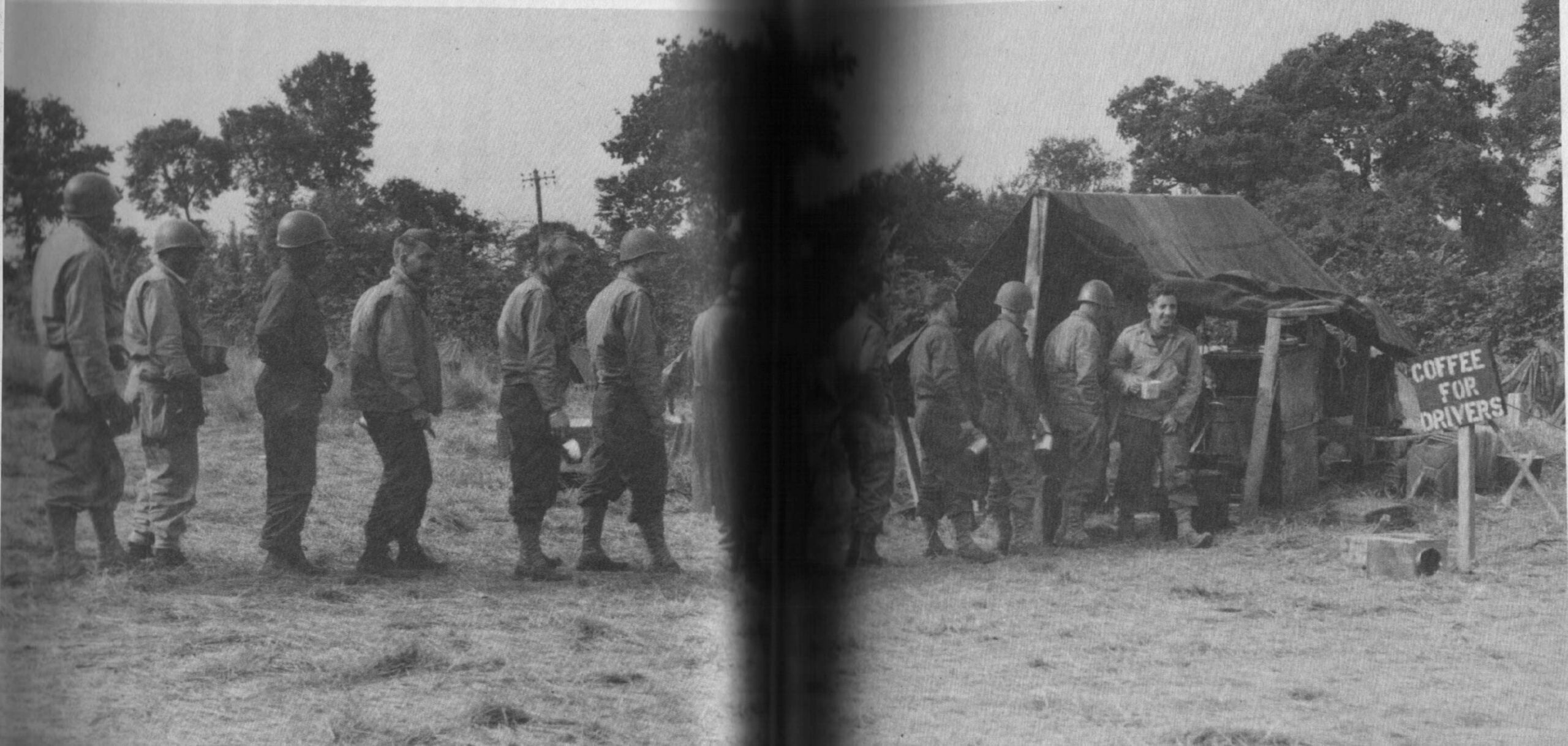
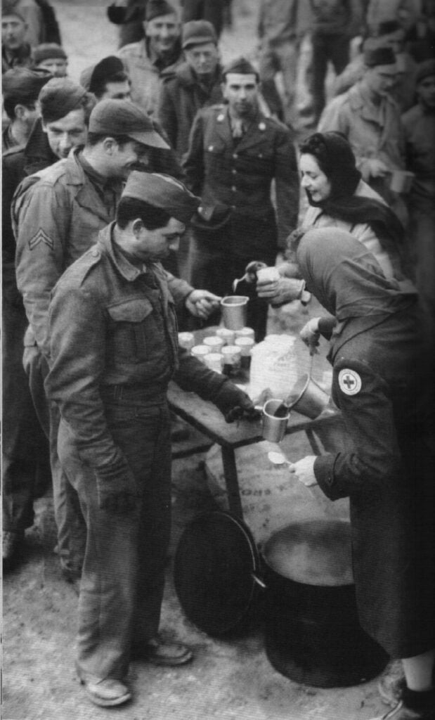
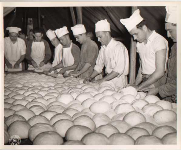
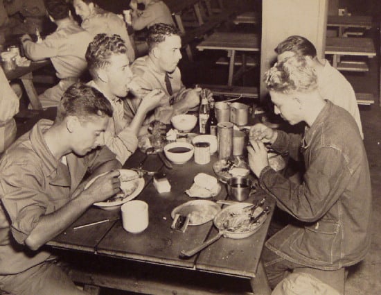
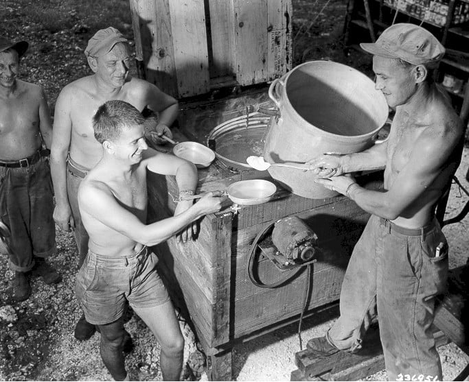
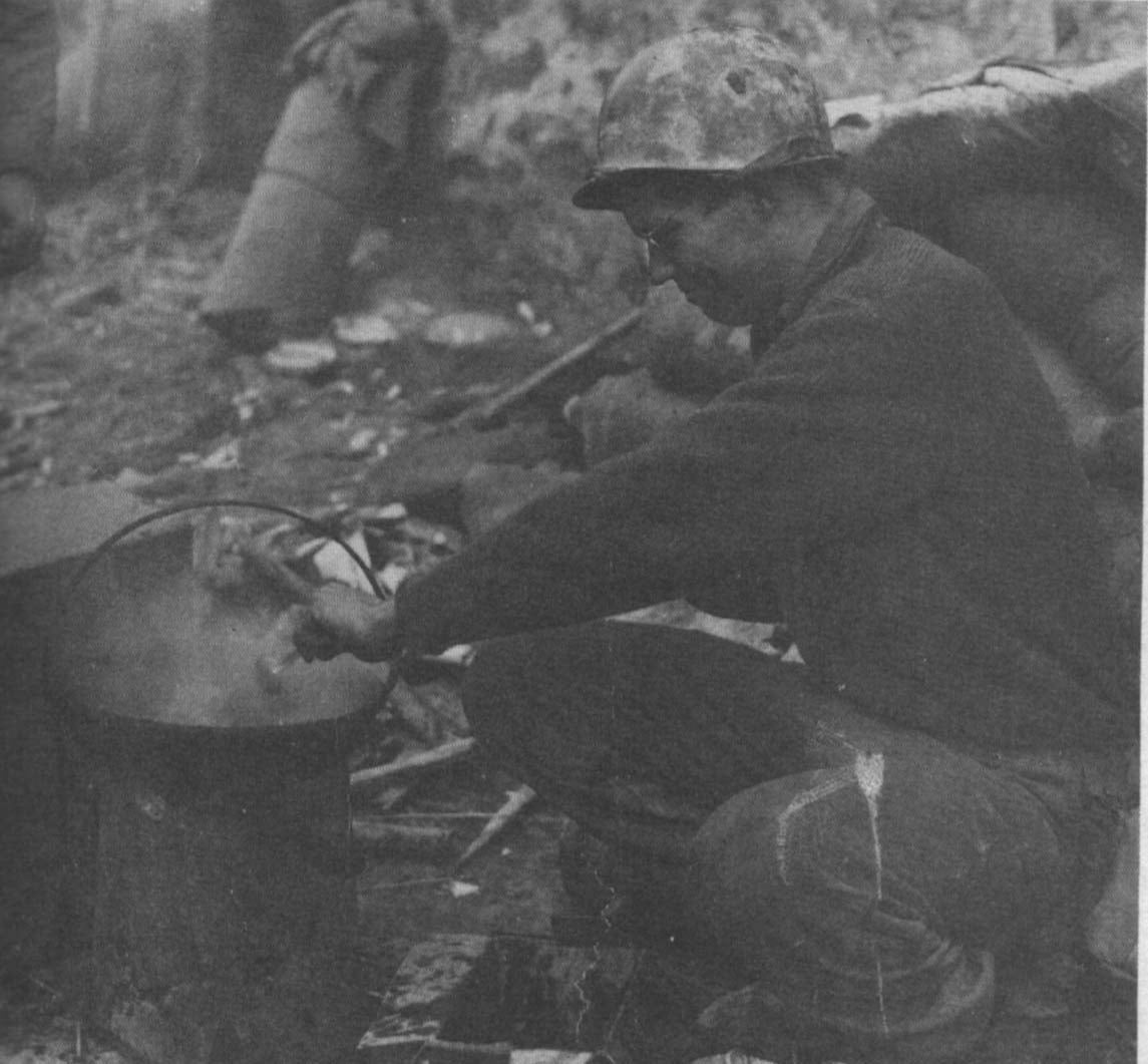
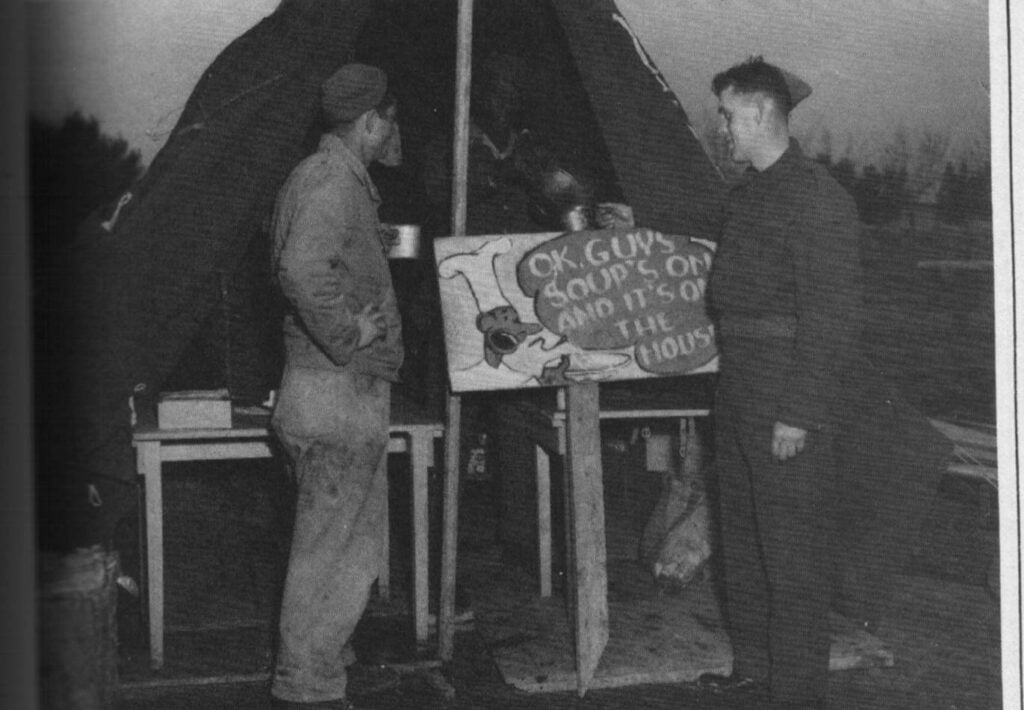
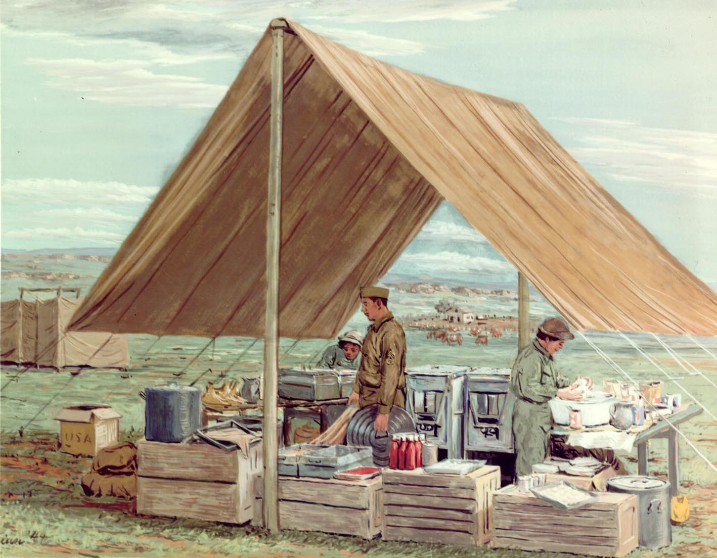
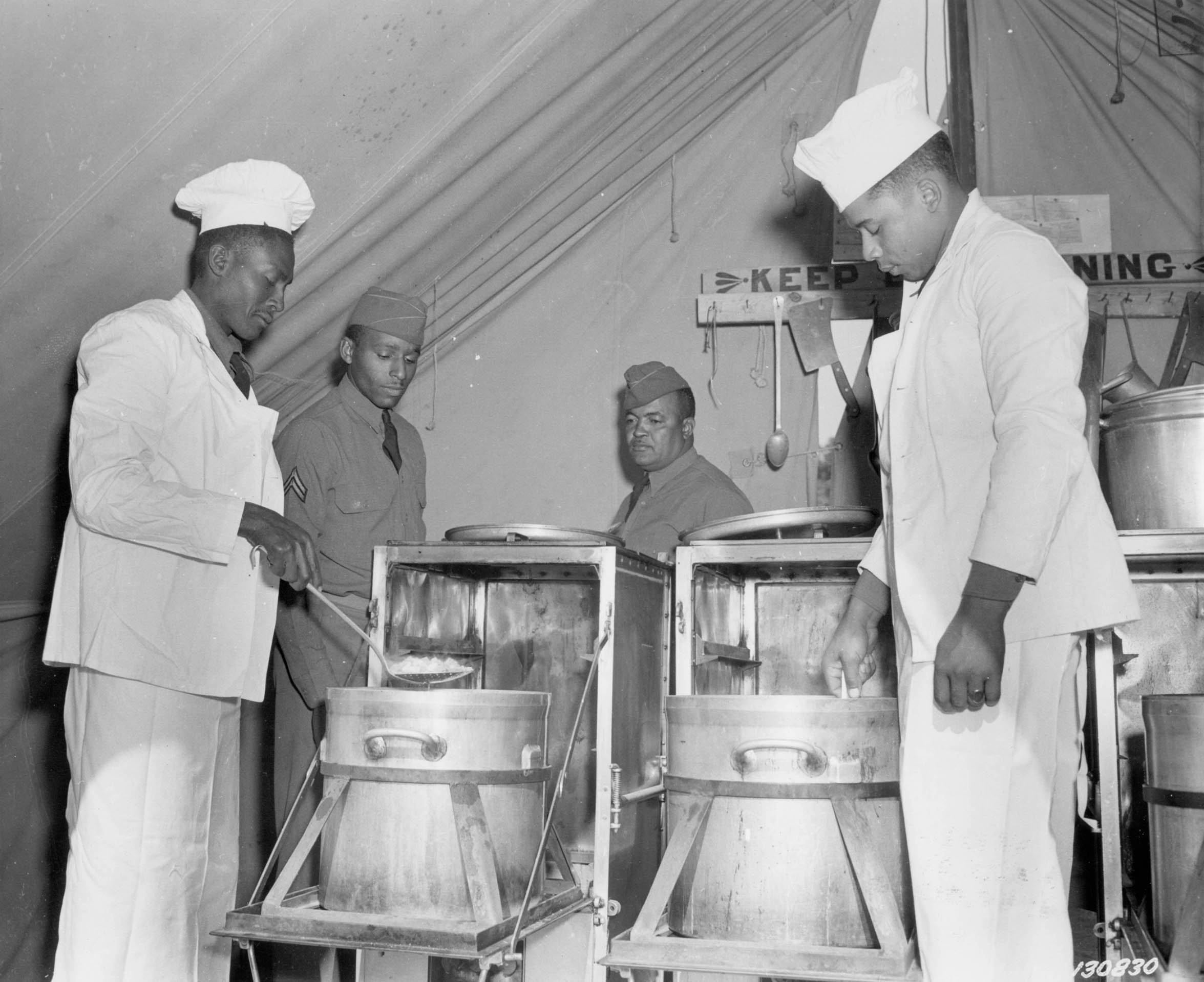
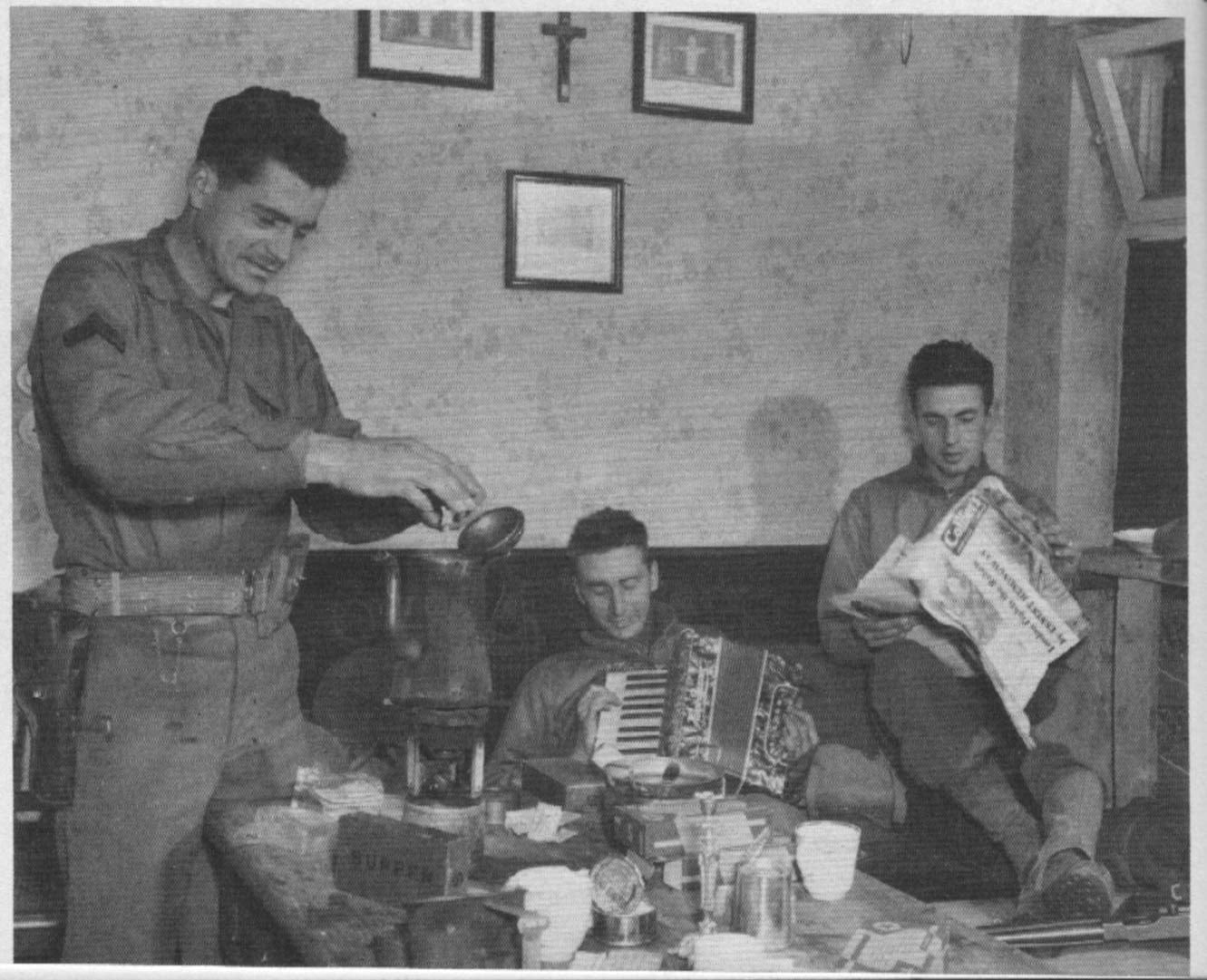
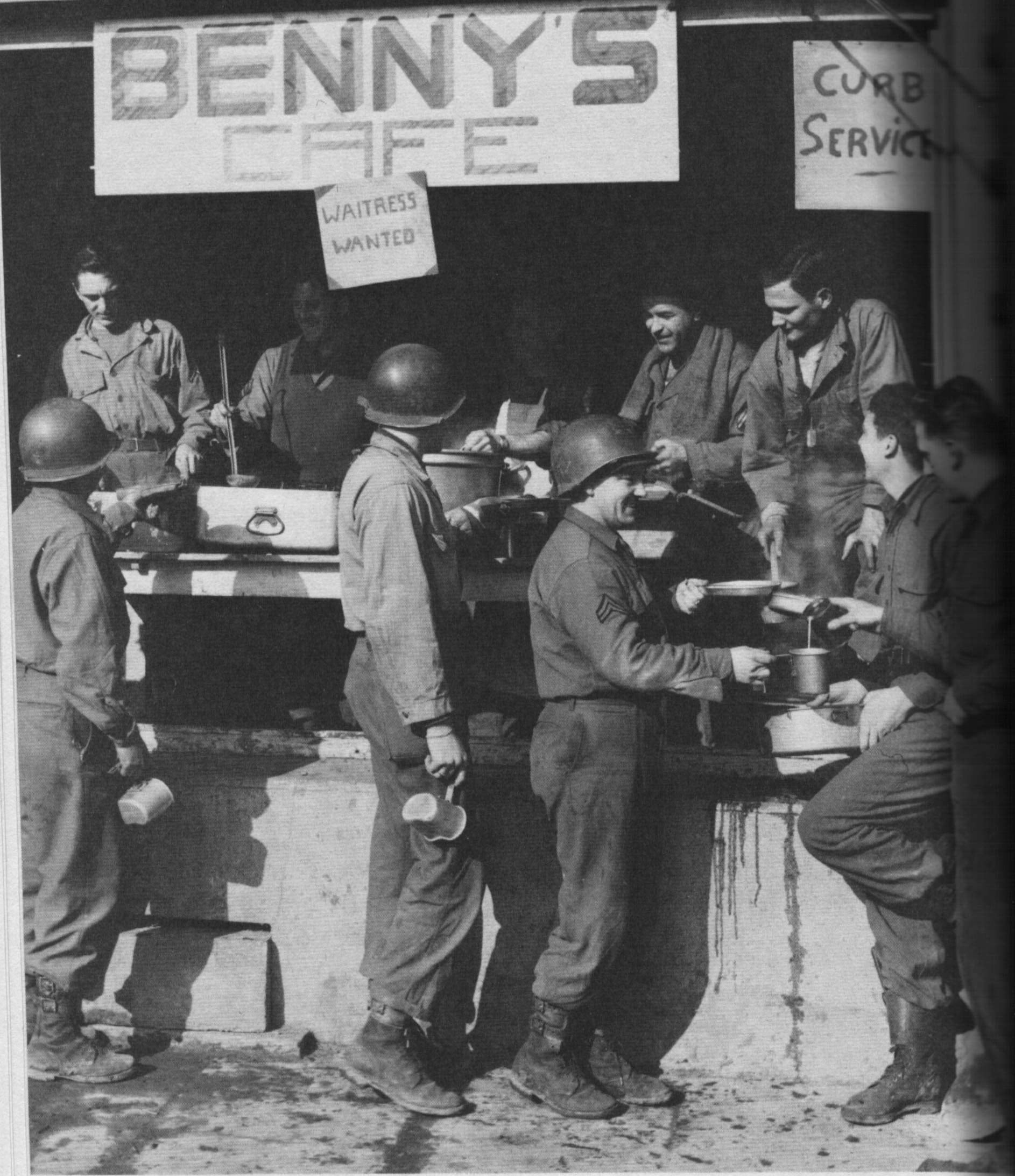
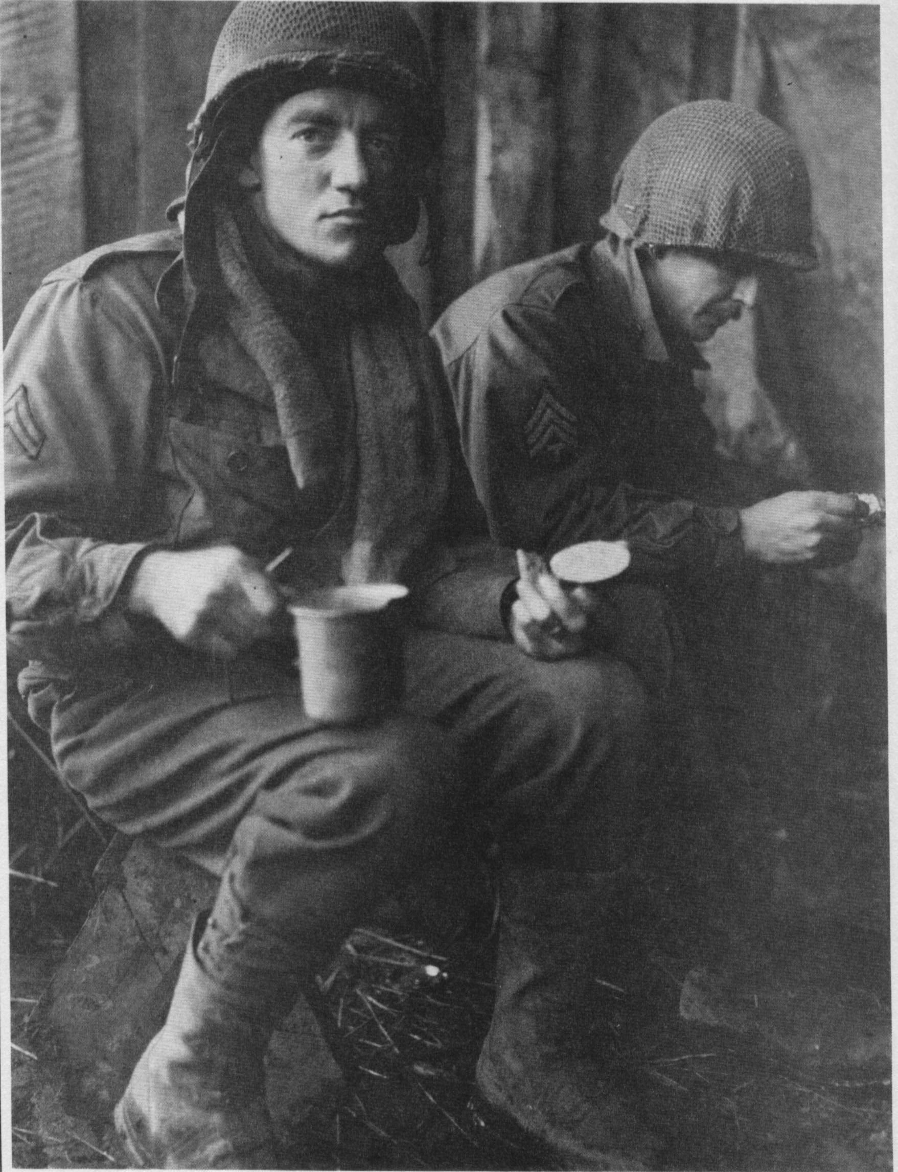
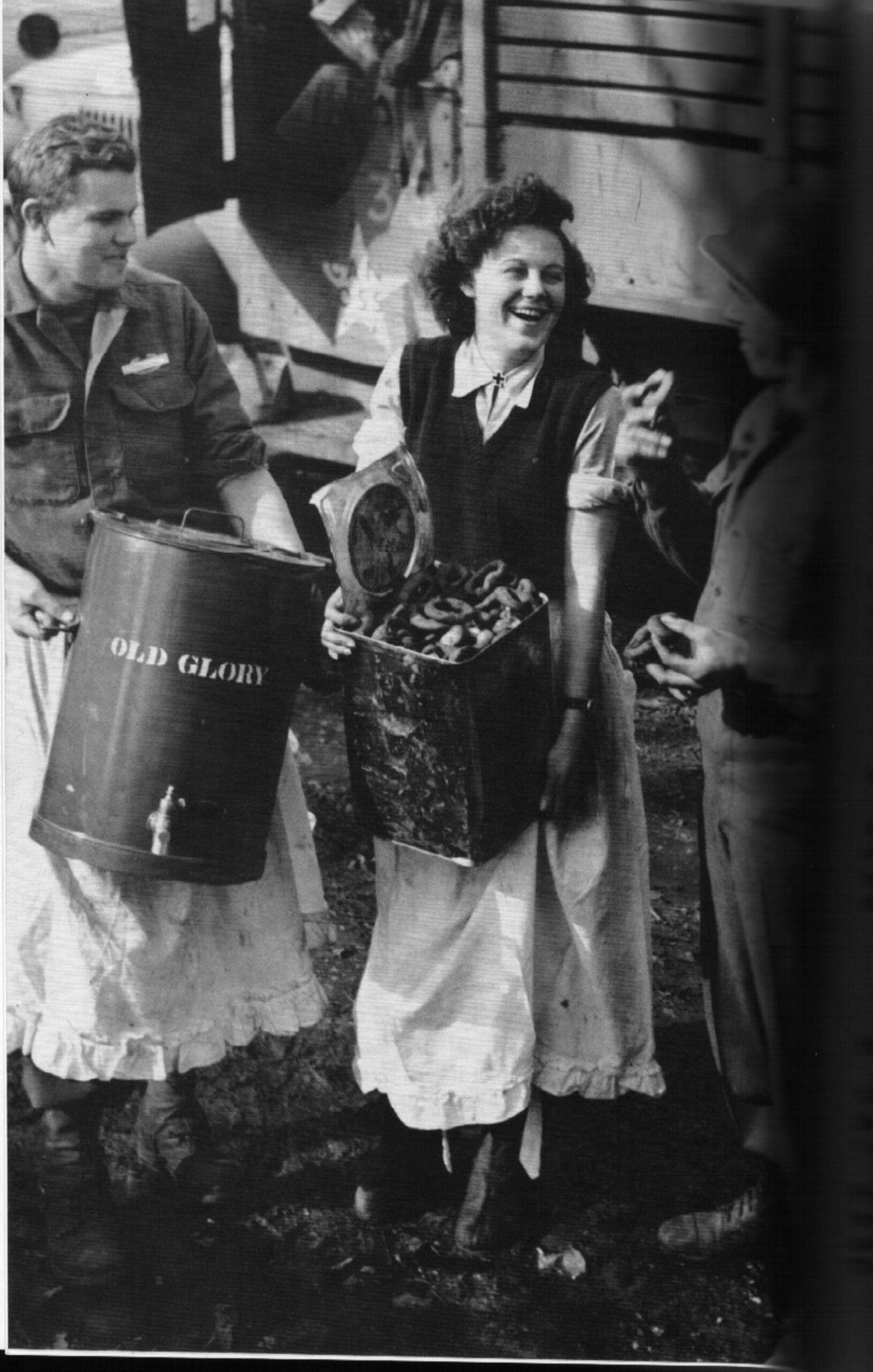
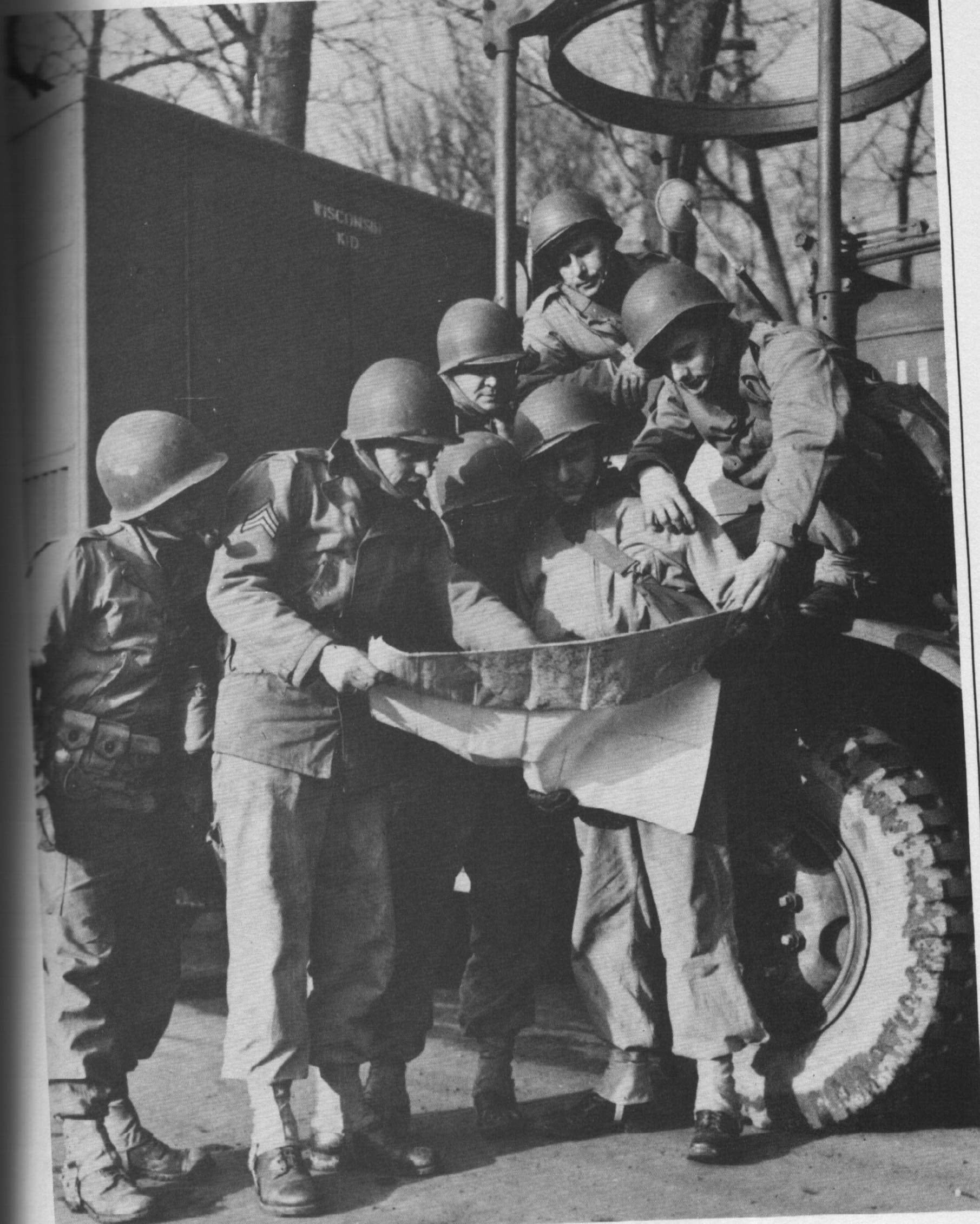
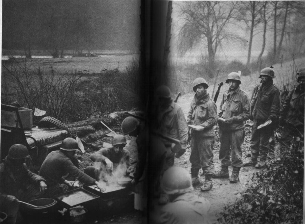
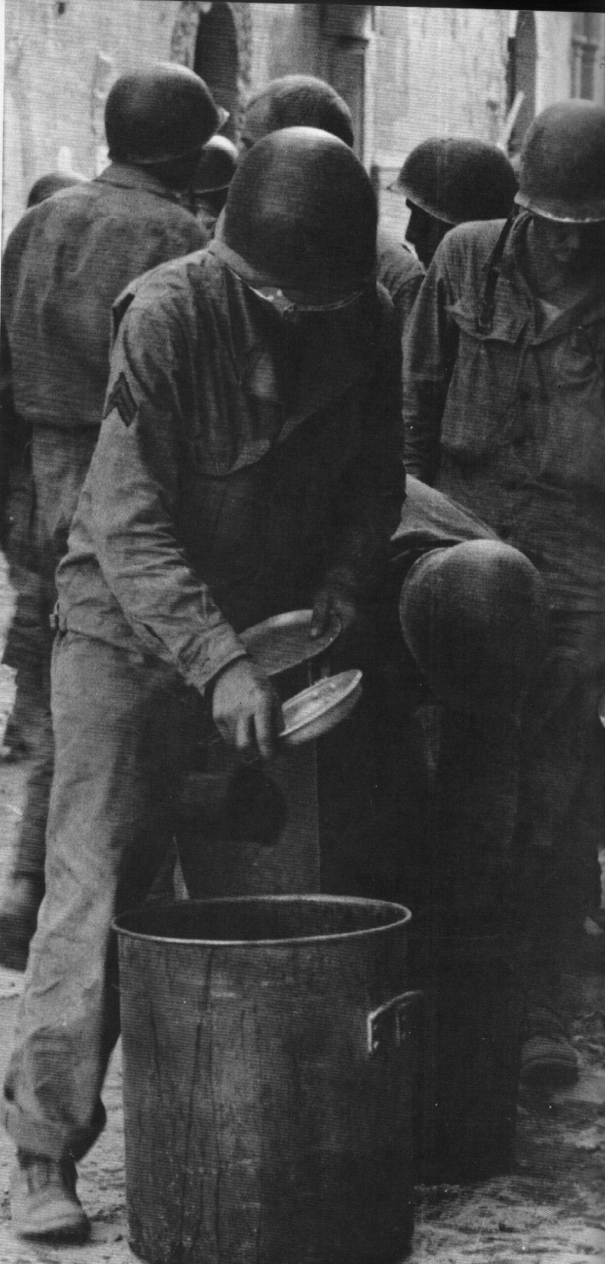
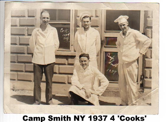
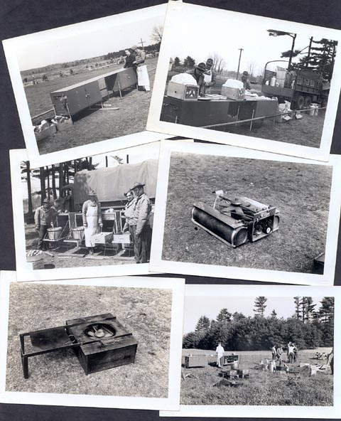
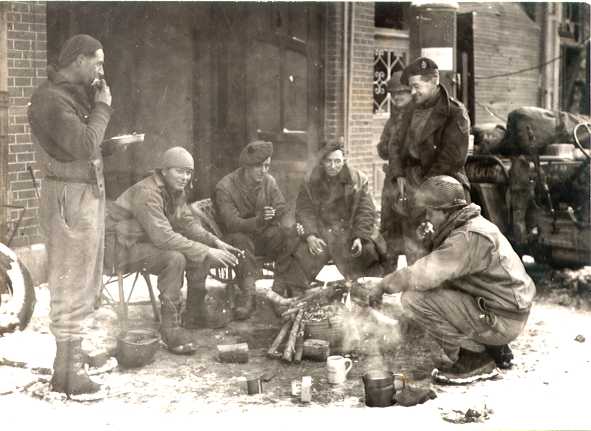
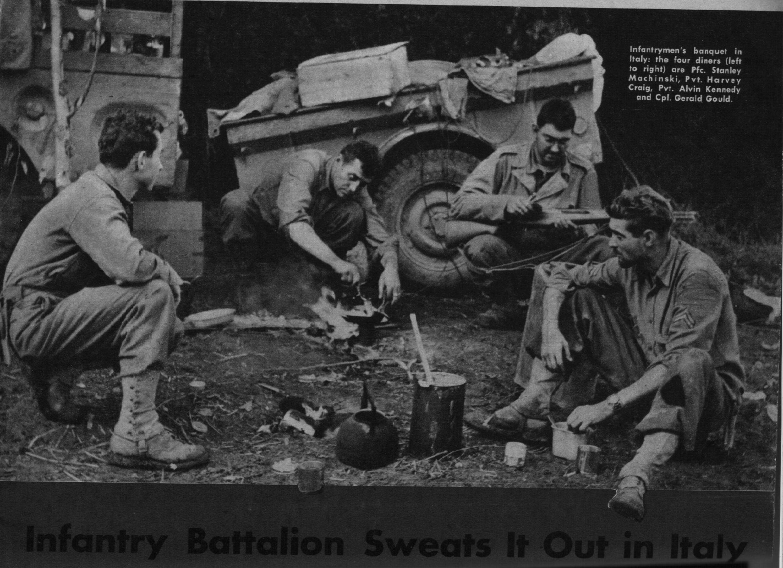
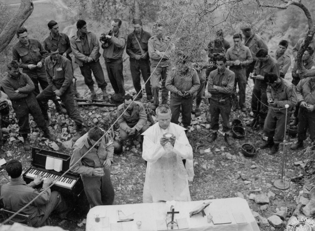
Images of Messes, Bakeries, and Soldiers in the Field Eating
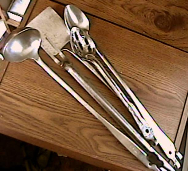
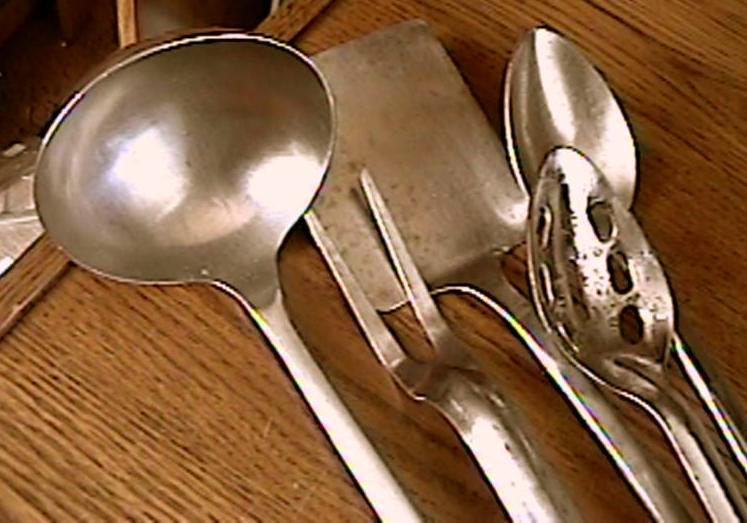
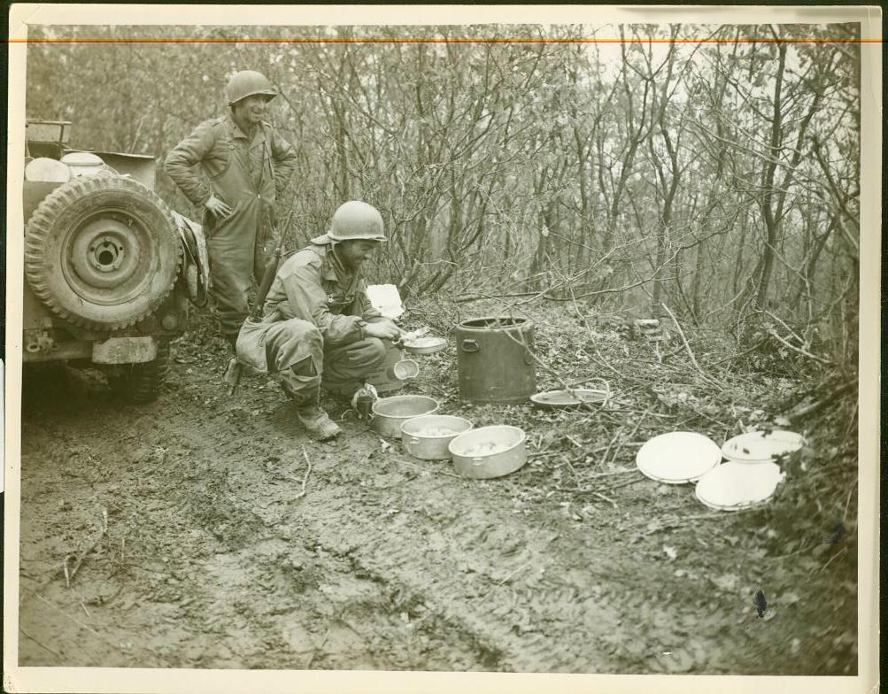
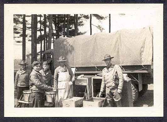
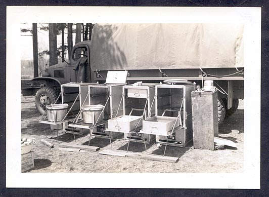
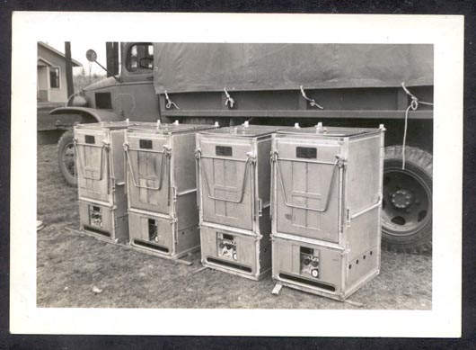
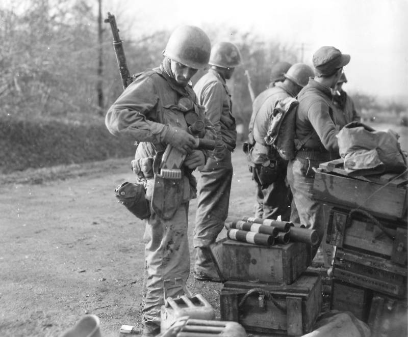
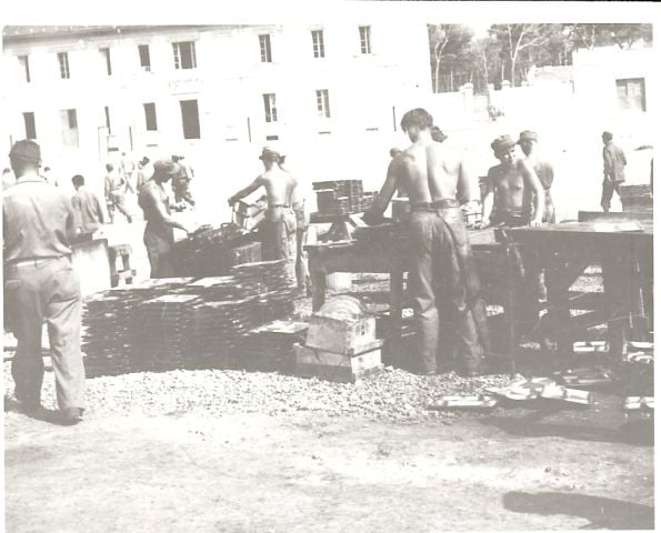
A really cool image of a small supply depot showing rations, water, and other items needed before heading out. The neat thing, too, is that the soldier uses the shovel cover as a holder.
Early in January 1944 it was established that razor blades had been used as an anti-sniper device in action against the Japanese. The insertion of several blades in trees which were likely to be used by enemy snipers provided an effective means of preventing these snipers from taking position in these trees after infiltrating through the lines at night.
Initially, investigation was made toward the possibility of utilizing tools similar to stapling tools and glazier’s point driving tools to accomplish the desired results. However, it was found that a fully automatic device based on such designs would be entirely too heavy.
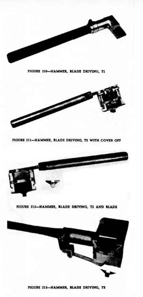
Further investigation and development resulted in the following described types of blade-driving hammers:
a. Hammer, Blade Driving, T1
A wood handle with a metal head which holds a triangular-shaped blade. Individual blades are inserted into trees by swinging the device in a manner similar to using a regular hammer. This item was developed by the Magazine Repeating Razor Company (Fig. 210).
b. Hammer, Blade Driving, T2
A metal handle with a metal head containing a magazine and feeding device. A single “T”-shaped blade is inserted into the tree with each stroke of the hammer head, the device recocking itself with each backward stroke. This item weighs 13½ pounds and was developed by the International Staple and Machine Company (Figs. 211 and 212).
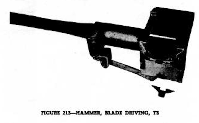
c. Hammer, Blade Driving, T3
A brass handle with a steel head containing a blade magazine. This device is semi-automatic in operation and is hand cocked each time it is desired to drive a blade into a tree. This item was also developed by the International Staple and Machine Company (fig. 213).
The T3 Blade Driving Hammer together with the specially designed blades were submitted in turn to Headquarters, Army Ground Forces and the U.S. Marine Corps who indicated that mechanical means were not required to accomplish the desired results and recommended that no further development be undertaken.
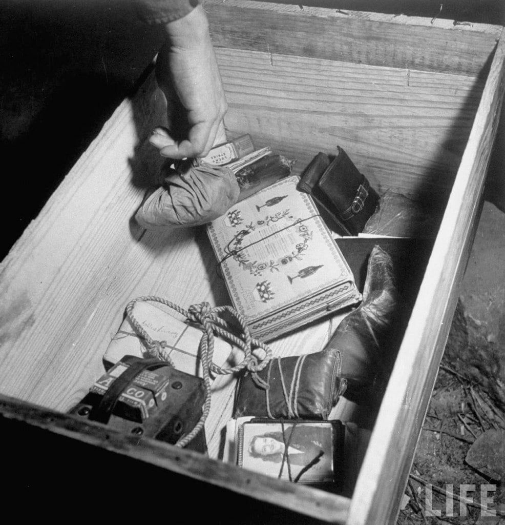
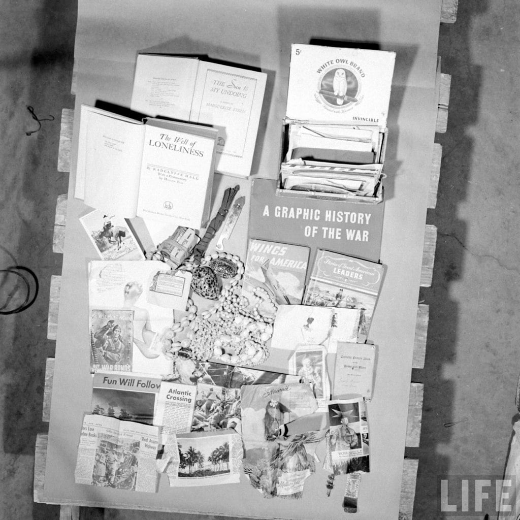
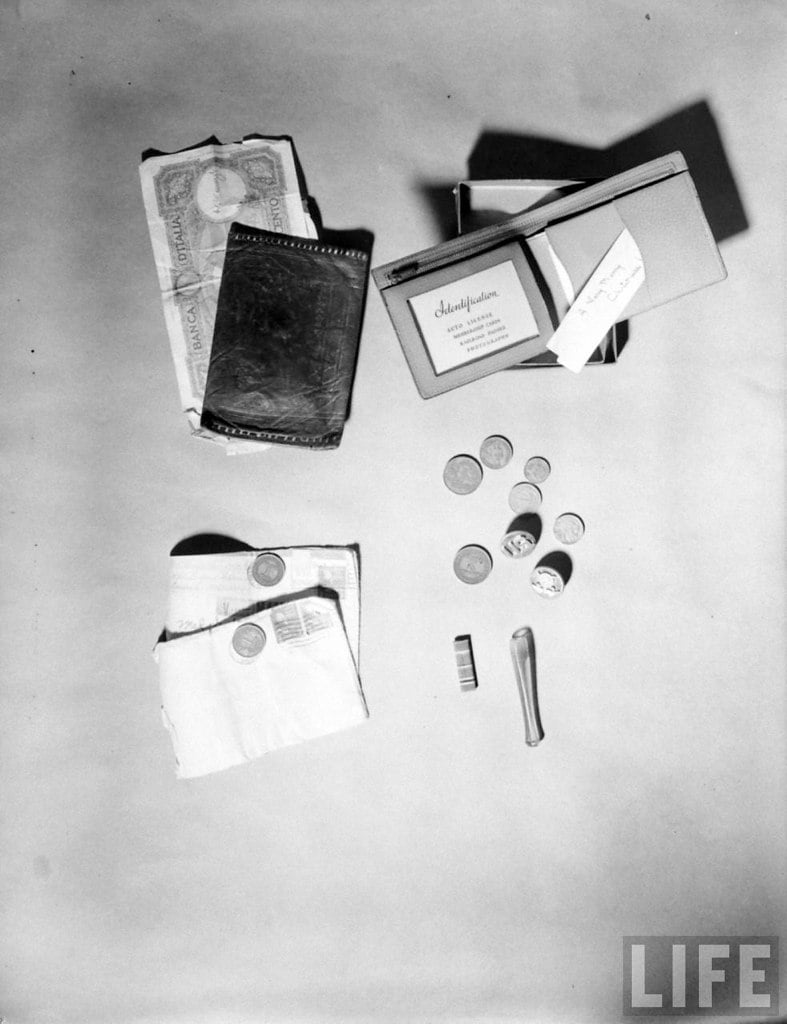
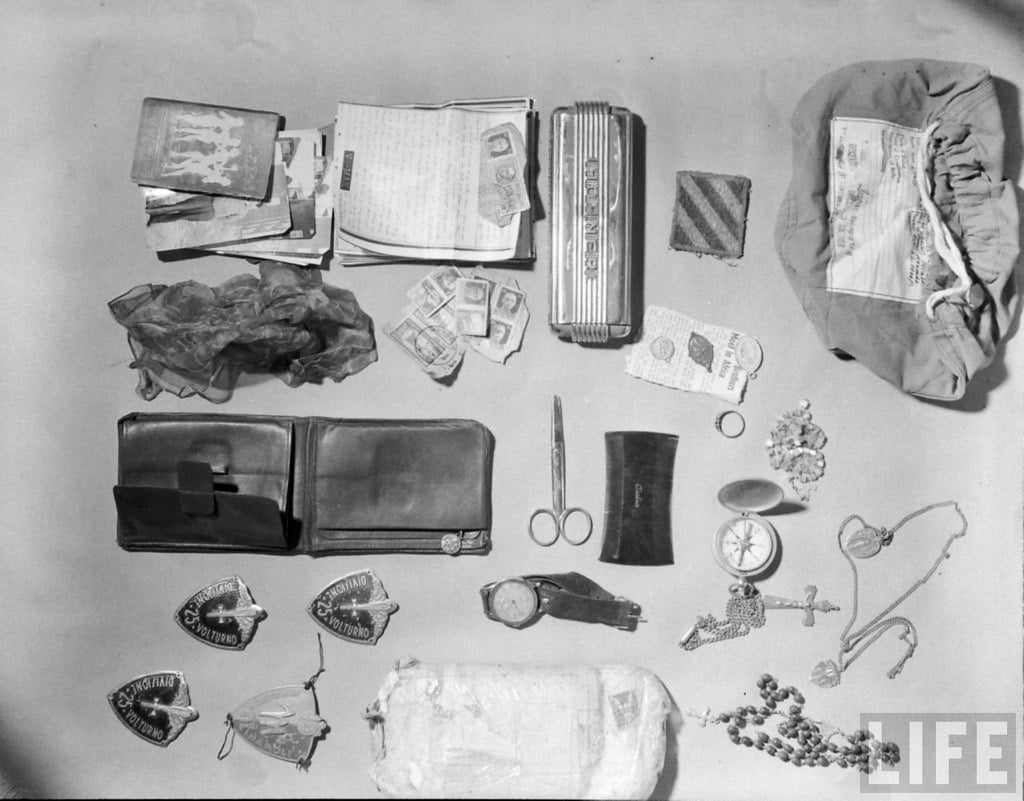
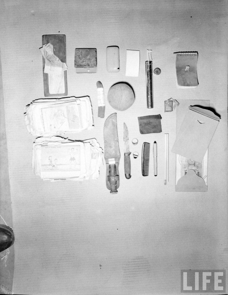
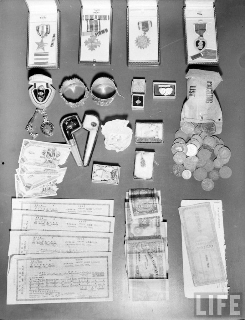
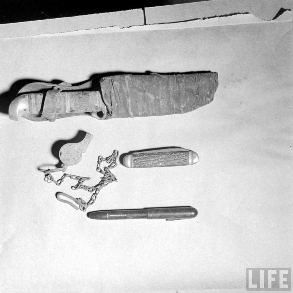
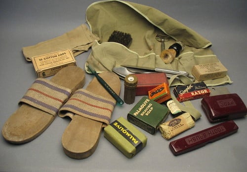
Below are some pictures from my personal archive of personal effects of soldiers in WW2. The Timelife ones are, I think, taken from airmen who perished during their mission.
The Timelife ones are, I think, taken from airmen who perished during their mission.
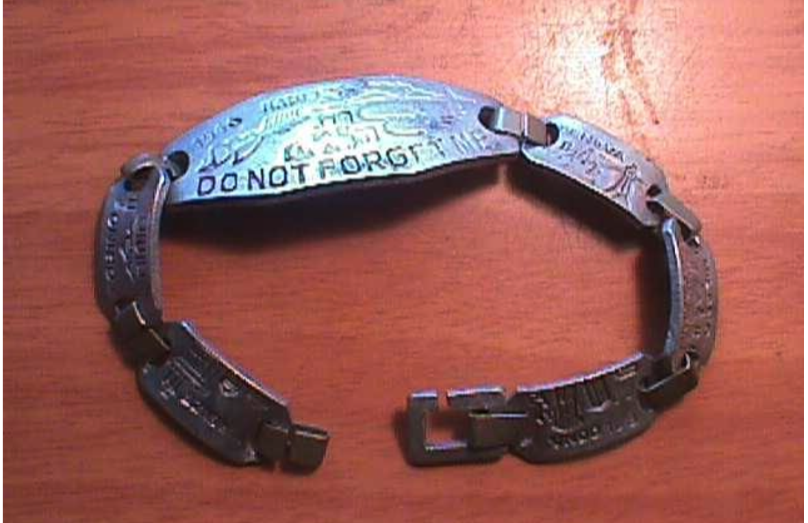
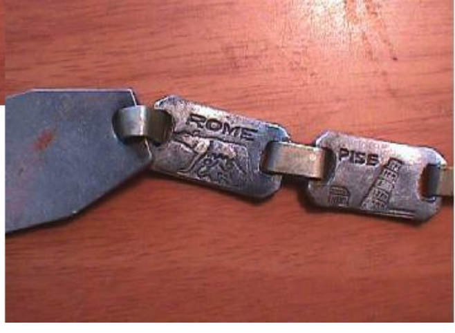
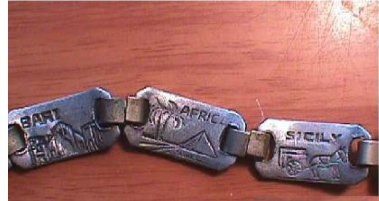
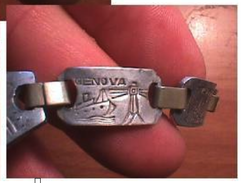
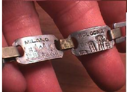
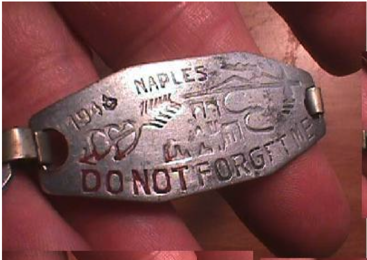
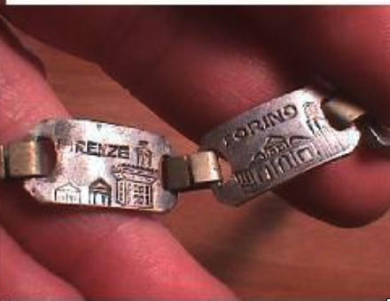
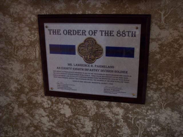
Bracelets – This is taken from an old eBay listing of the 88th Infantry Division, 351st Regiment. Made of maybe aluminum. Shows a timeline of their service in Italy.
There’s often been a discussion of weight as it pertains to soldiers in WW2. The US Army had height and weight requirements, but I suspect wartime demands may have overlooked them for certain situations.
Indeed, the US Army had a set of Mobilization Regulations No 1-9 created in Aug 1940 that set physical standards –
Arguably, I think you’d be in a tough position to prove that an exceptionally tall or exceptionally overweight soldier would be on the front line in a foxhole. However, there’s enough evidence that such soldiers did fight in WW2, but likely in a rear or support position.
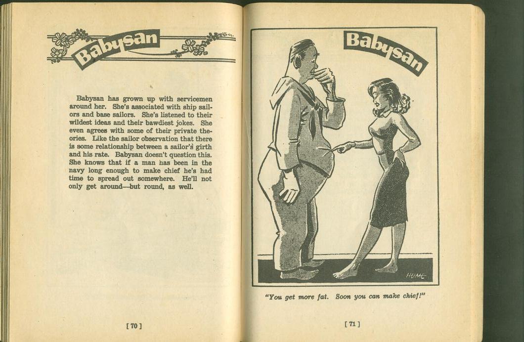
Indeed, there are a few publications that created humorous cartoons alluding to this fact (especially with the Navy).
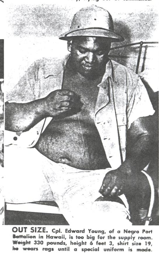
Cpl Edward Young of the Nergo Port Battalion in Hawaii is probably the heaviest African-American, weighing in at 330 pounds.
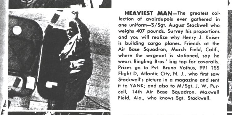
S/Sgt August Stackwell from the Air Base Squadron in March Field, CA, is likely the heaviest white soldier, weighing in at 407 pounds.
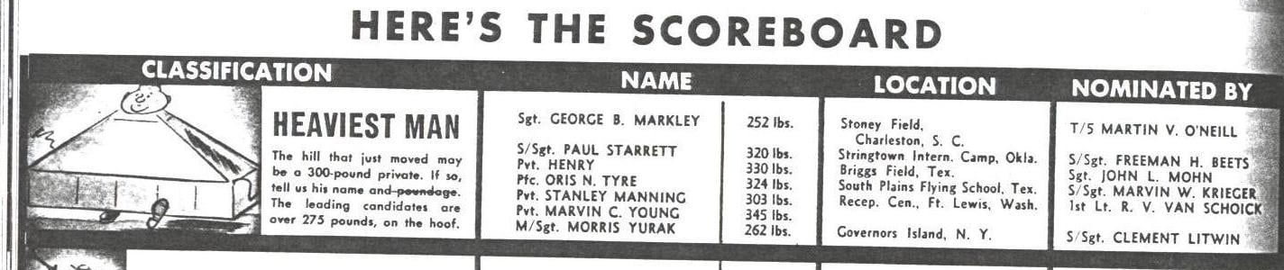
Yank Magazine also profiled a few persons and collected nominations for who the heaviest soldiers are.
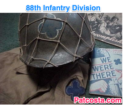
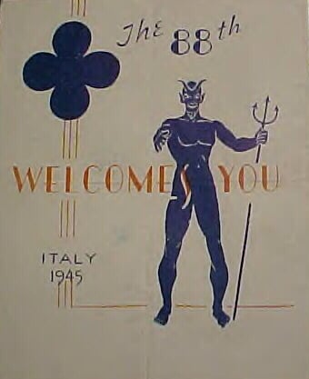
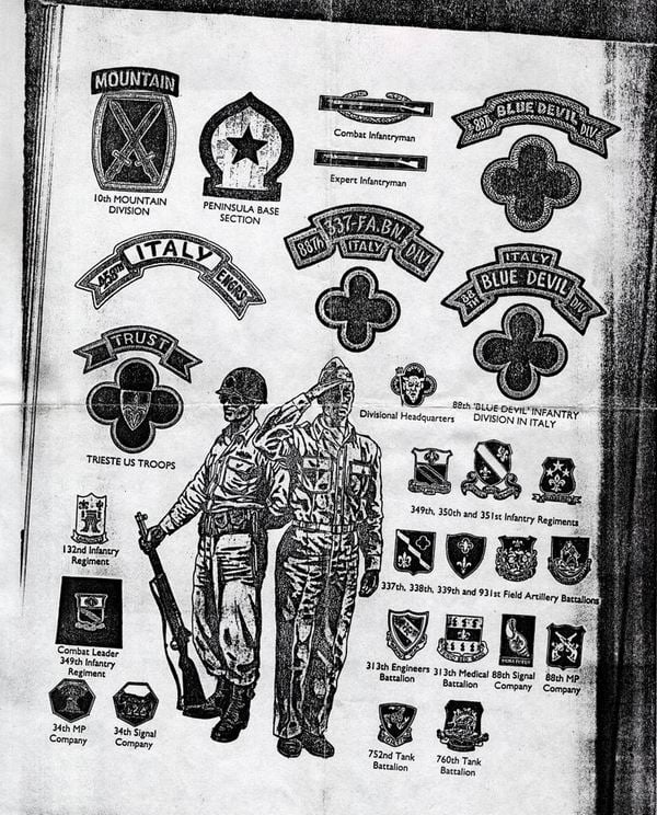
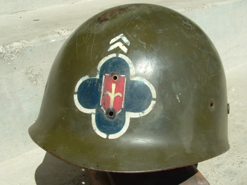
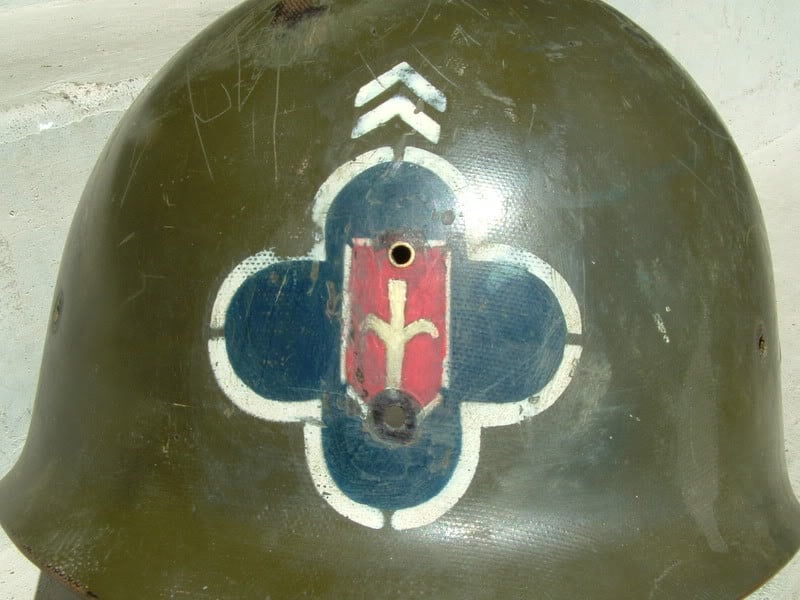
When I first started reenacting, this was the unit my friends and I decided to reenact. It was a draftee division made up of average Americans, and we thought it fitting. Over the years, I’ve collected lots of information related to this unit, and I’ll be putting it here.
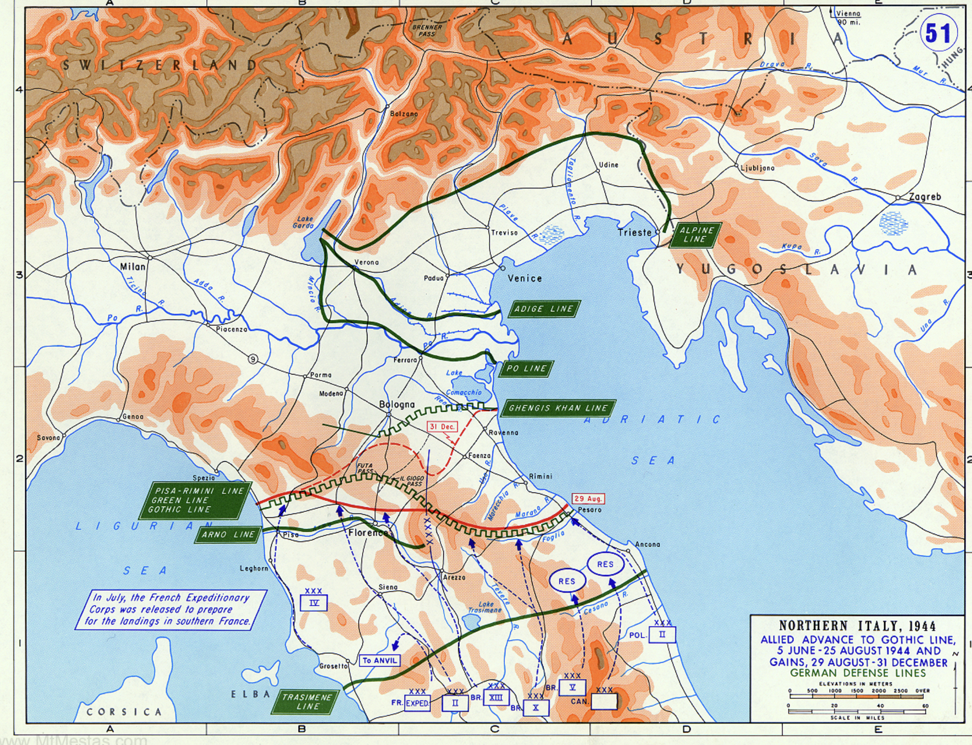
German 71st Division (oppositte 88th on Gustav Line)
1060th Panzergreninder Regiment
1st Parachute Regiment
4th Parachute Regiment
1st parachute division (Major General Schulz; we fought them at Battle Mt) (nickname: GREEN DEVILS)
305 Infanry Divison: Major General Von Schellwitz
8th Mt. Division (Major General Schricker)
Some Notes I have
31st US Infantry Division: 88th regarded as its personal enemy (since LA maneuvers)
US Units in Italy with 88th: 85th, 91st, 9th, 1st 3rd, 36th, 45th, 10th Mt, 92nd, British 5th Division, French Corps were under General Alphonse Juin, Brazilina Expeditionary Force, 6th South-Africans and British 1st Division which was with 88th for Gothic Line Assualt.
The 7th Army was formed for Invasion of Southern France: Units were 3rd, 36th, 45th Divisions.
The 103rd Infantry Division met the 88th a few miles south of Brenner Pass
Was part of II Corps: 88th, 85th, 3rd Infantry and 1st Special Service Force. Was part of 5th Army
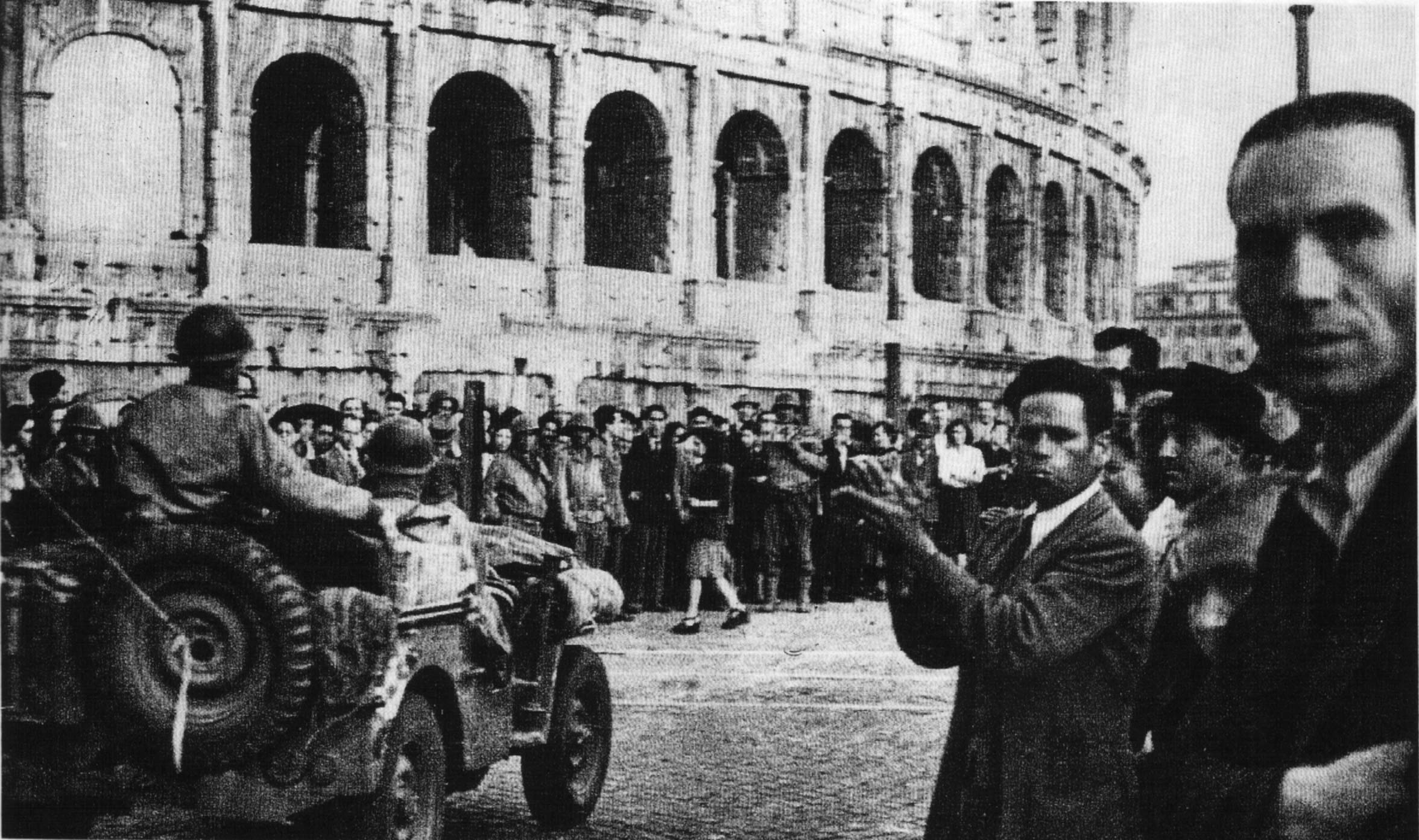
88th Recon Troop first in Rome, July 4th 0715hrs
Rome Area Allied Command GI Restaurant served meatloaf, string beans, asparagus, salad, bread/butter and coffee.
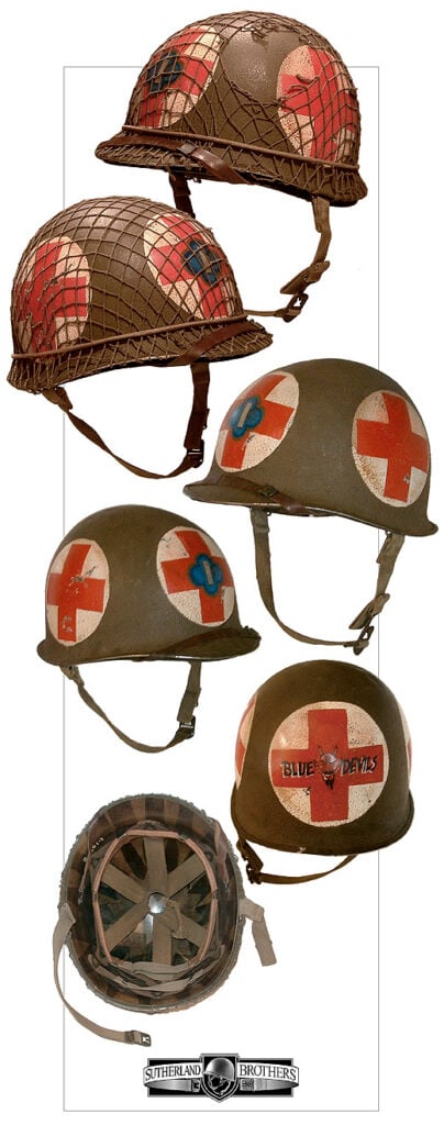
Bluedevil Rest Center was in Montecatini consisted of 3 hotels. It was located in Tuscany, 20 miles northwest of Florence. It is situated on the Austostrada that connects Florence to Pisa, just west of Pistoia. Today the highway is A11. Before the war it was the location of a spa.
The rest center was home to the Trianon Theater. The theater did 2 performances a night, and could hold 1,000 men. Drinks were 30 cents for rum, whiskey, and cognac, and champagne was sold by the bottle. Fights broke out just about every night between the Red bulls (34th), Pine Trees (?) and of course, the Bluedevils. Soliders could by knick-knacks, vino, roasted chestnuts from various civilians while relaxing in Montecatini.
The Fifth Army Red Cross set up “The Tent Club” and soon had one of the best clubs operating. The best attraction of the club was the ‘Jitterbug Queen” Mississippi (Ann Jenkins of Alabama).
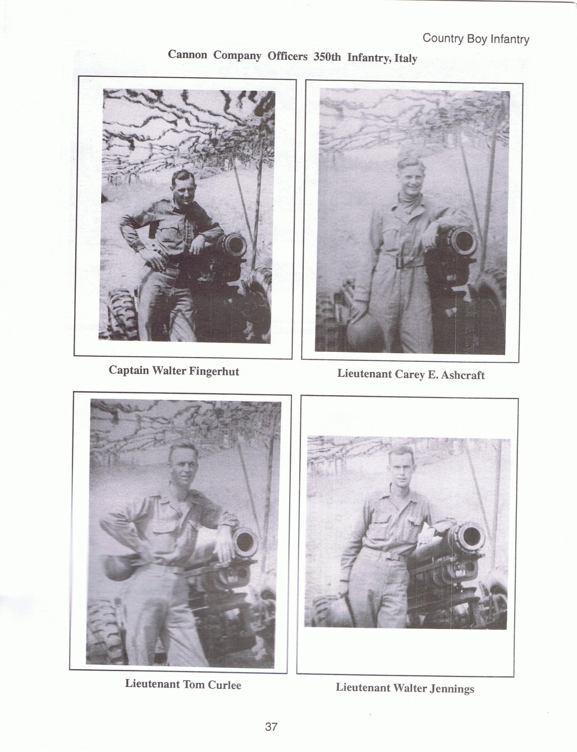
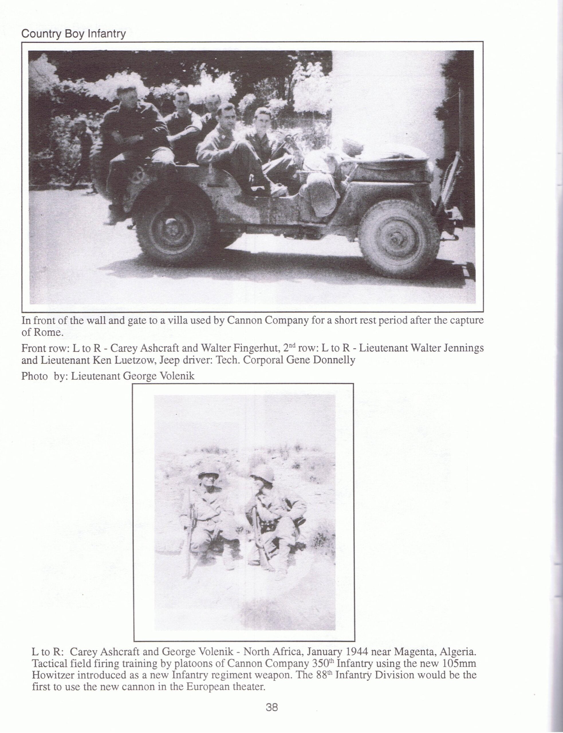
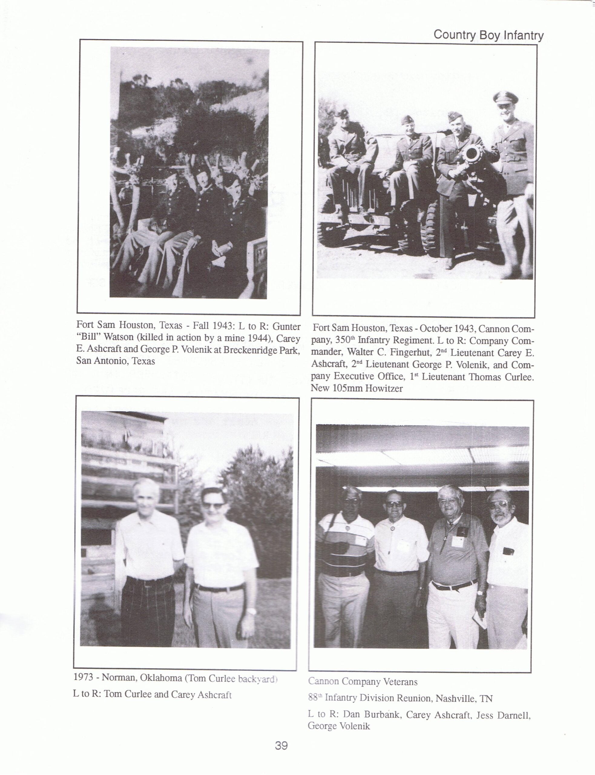
Country Boy Infantry: Bluedevils 88th Infantry, 1944-1945 by Carey E. Ashcroft. Yellow Springs, OH: Keahey Graphics, 1997. – Images are taken from that book. Consists of a narrative of the 350th Cannon Company.
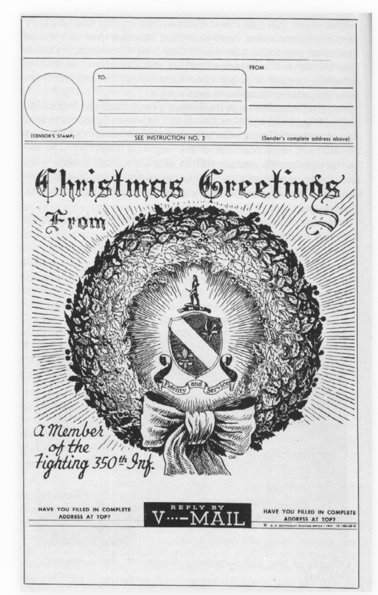
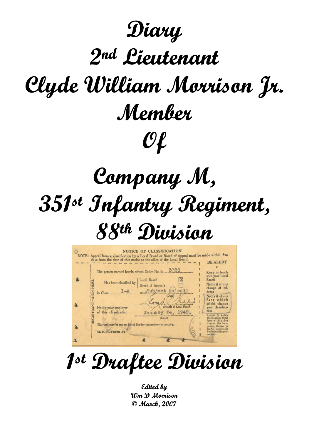
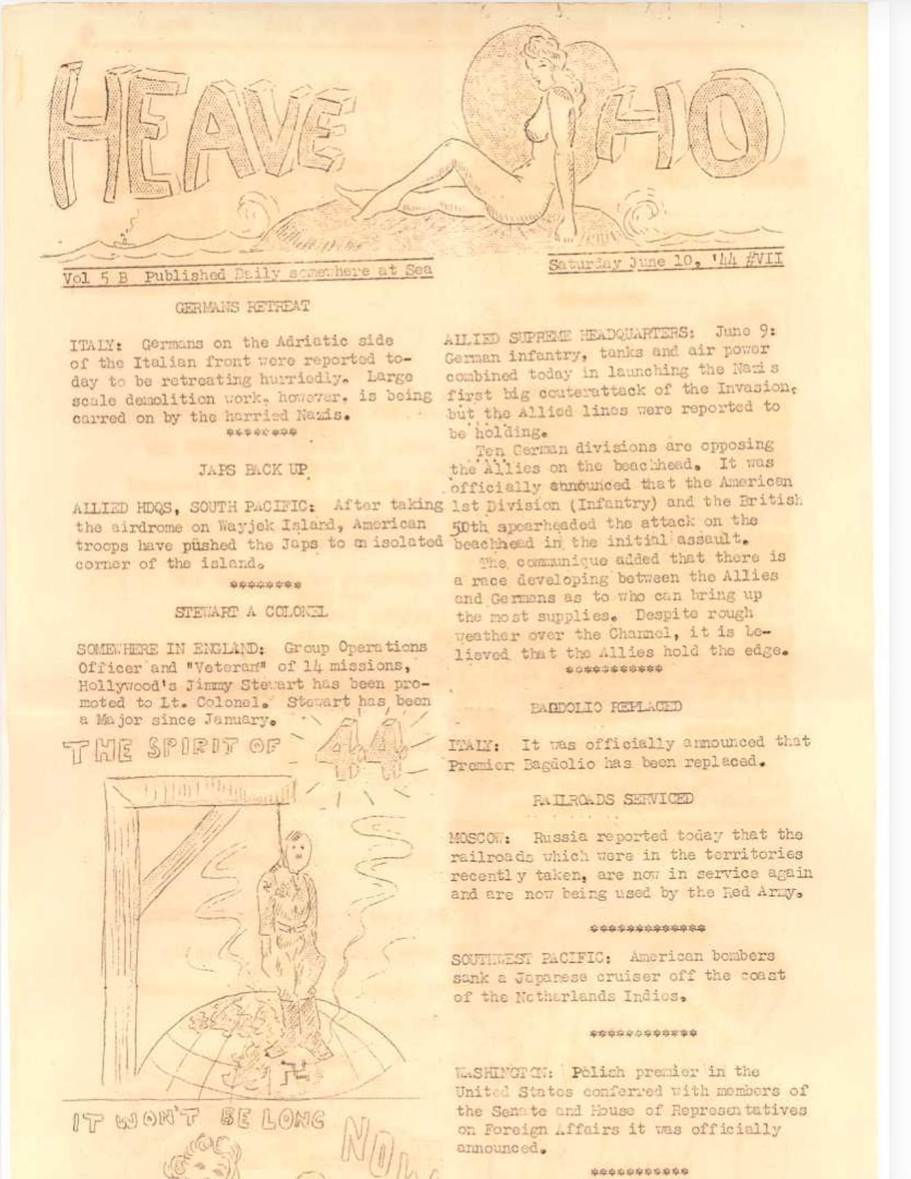
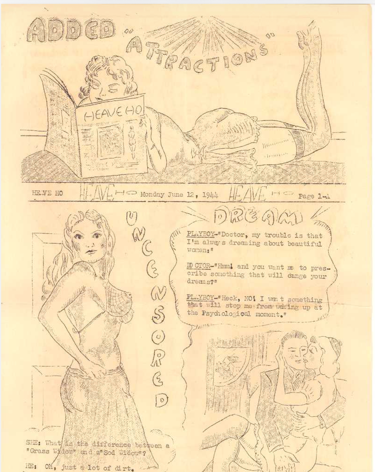
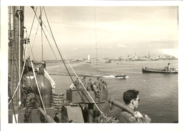
2nd Lt Clyde William Morrison Jr, Co M 351st Infantry Regiment – Diary account of time in service. Includes a few Heave Ho scanned publications at the end. Heave Ho was a publication made either by the soldiers on the ship or the navy personnel to help pass the time on the voyage back to the States. A few racy and nude drawings are included.
Leonard J. Dziabas, H Company, 351st Infantry Regiment – This is some personal correspondence I had with him back in 2003. He’s been featured in a few documentaries and other interviews, such as this Witness to War one.
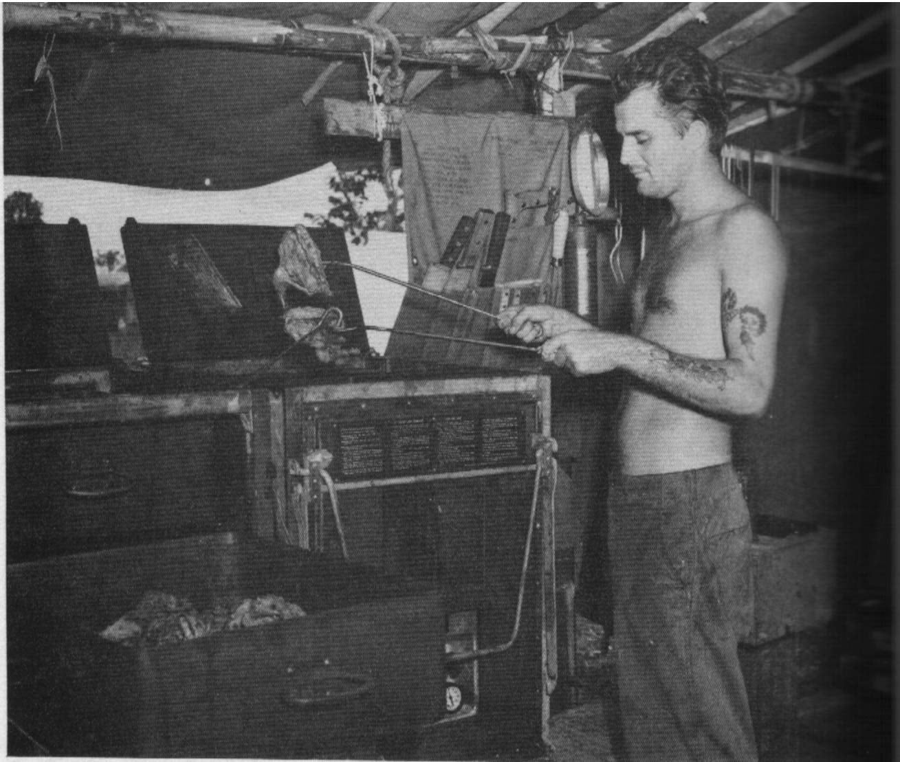
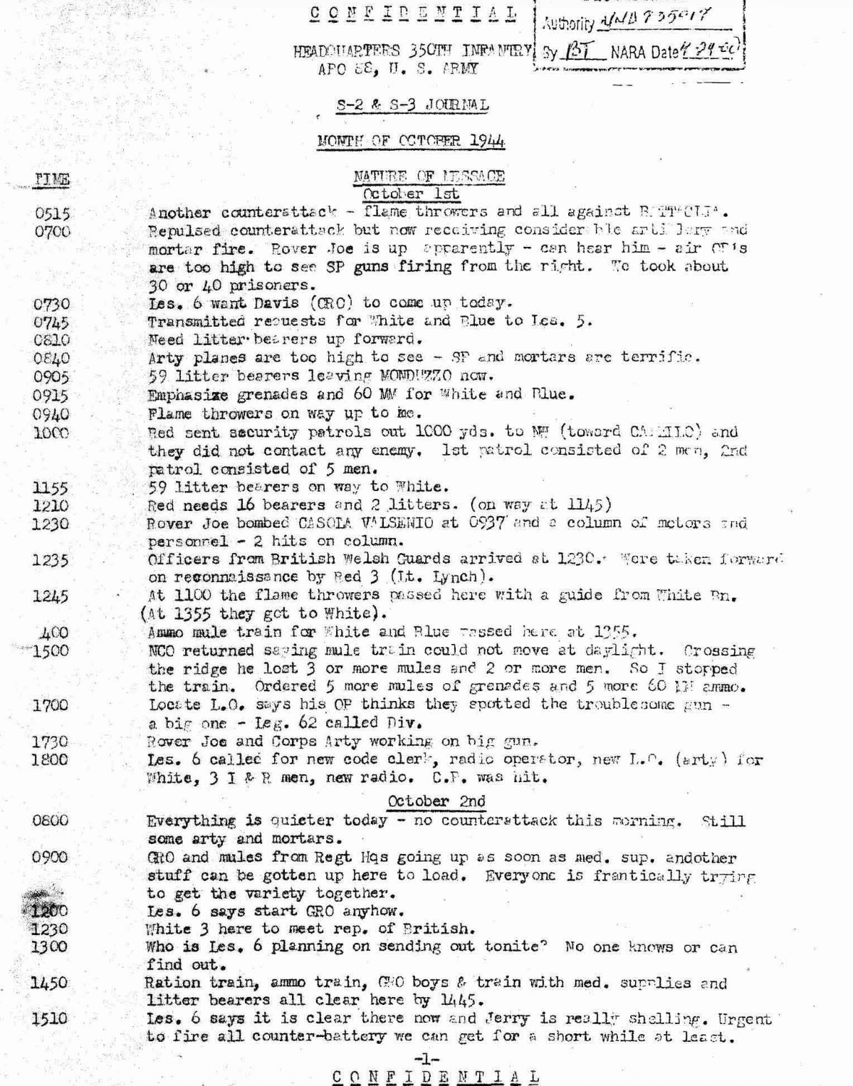
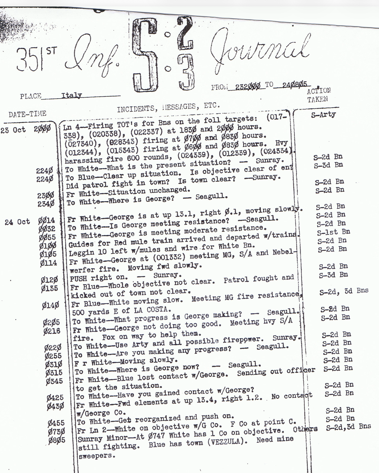
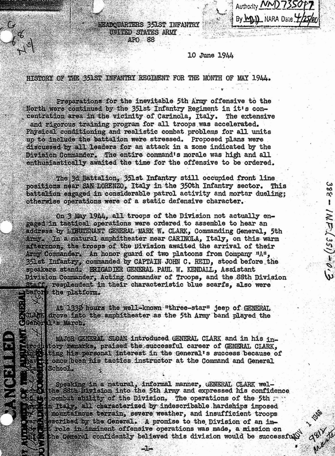
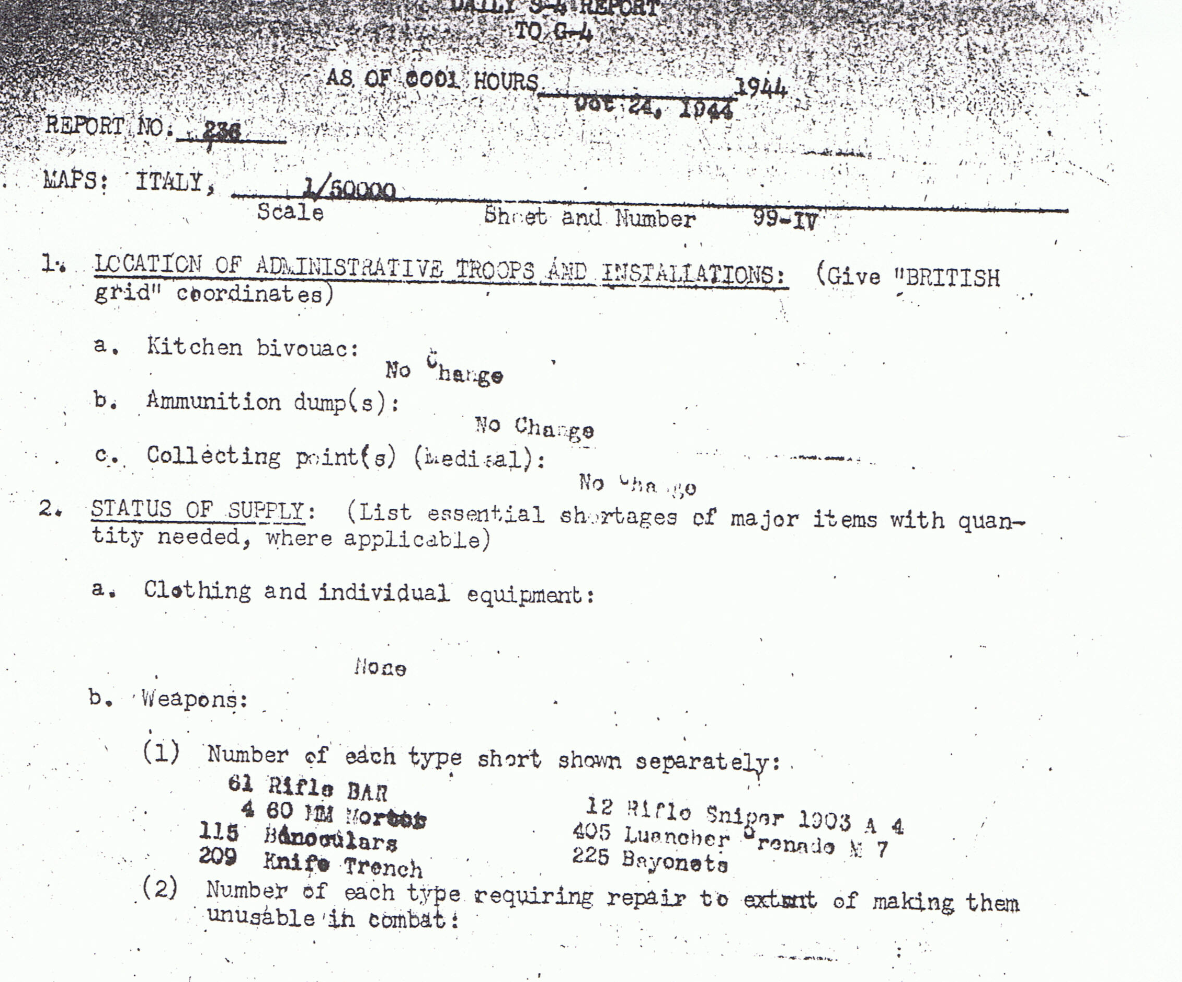
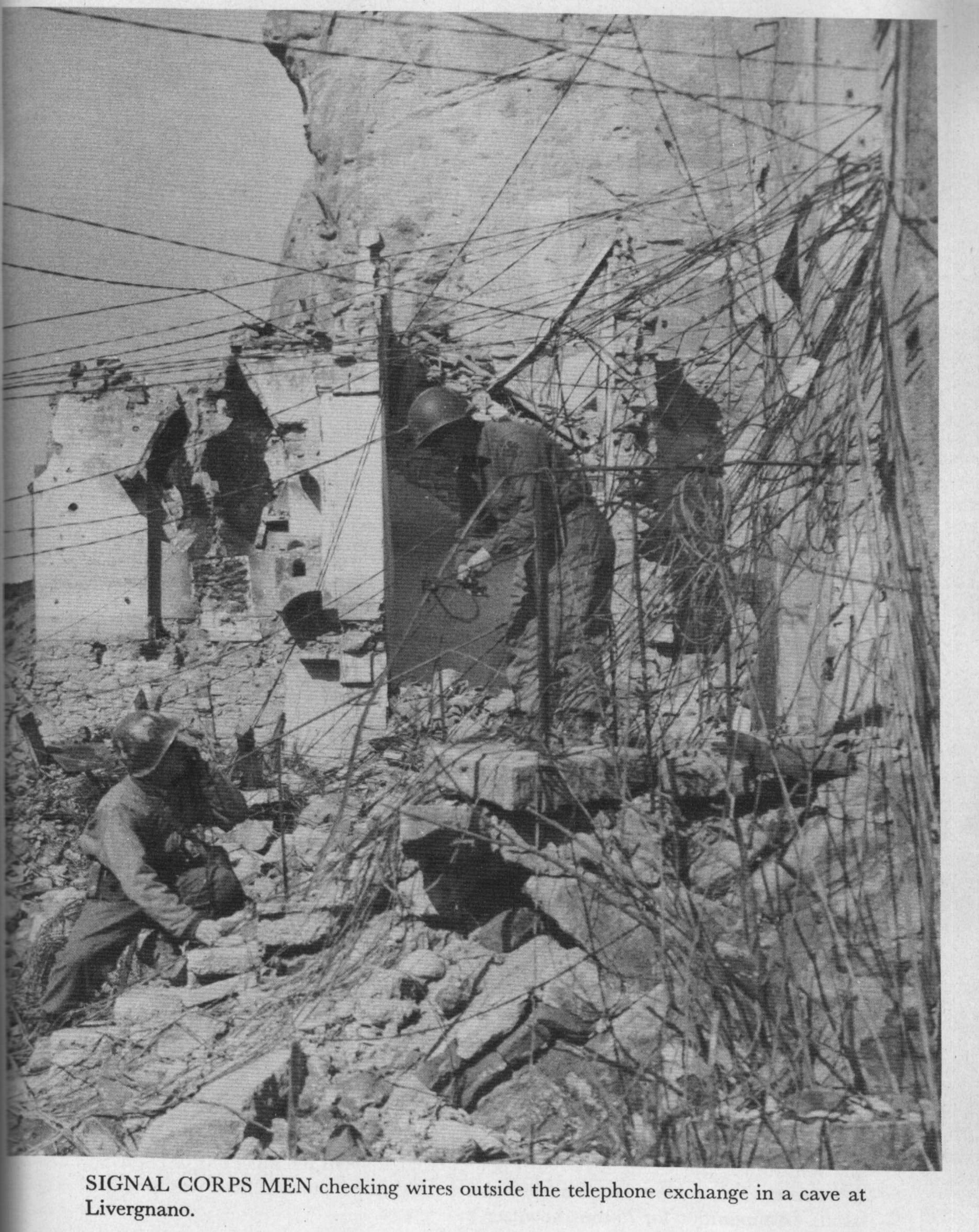
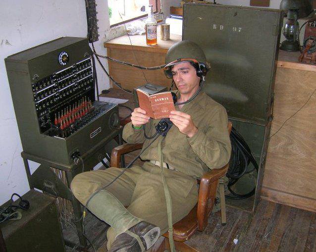
351st S-2 Journal Oct 23rd and 24th 1944 – A neat example of a probable radio operator (though it could be wire!) listening to radio traffic and transcribing it. This is probably at the regimental level as the regiment is communicating with different battalions (white and blue).
What’s hilarious is that someone obviously asked about getting pin-ups, and it has to be explicitly mentioned that “the battalion does not anticipate reproducing pin-ups.”
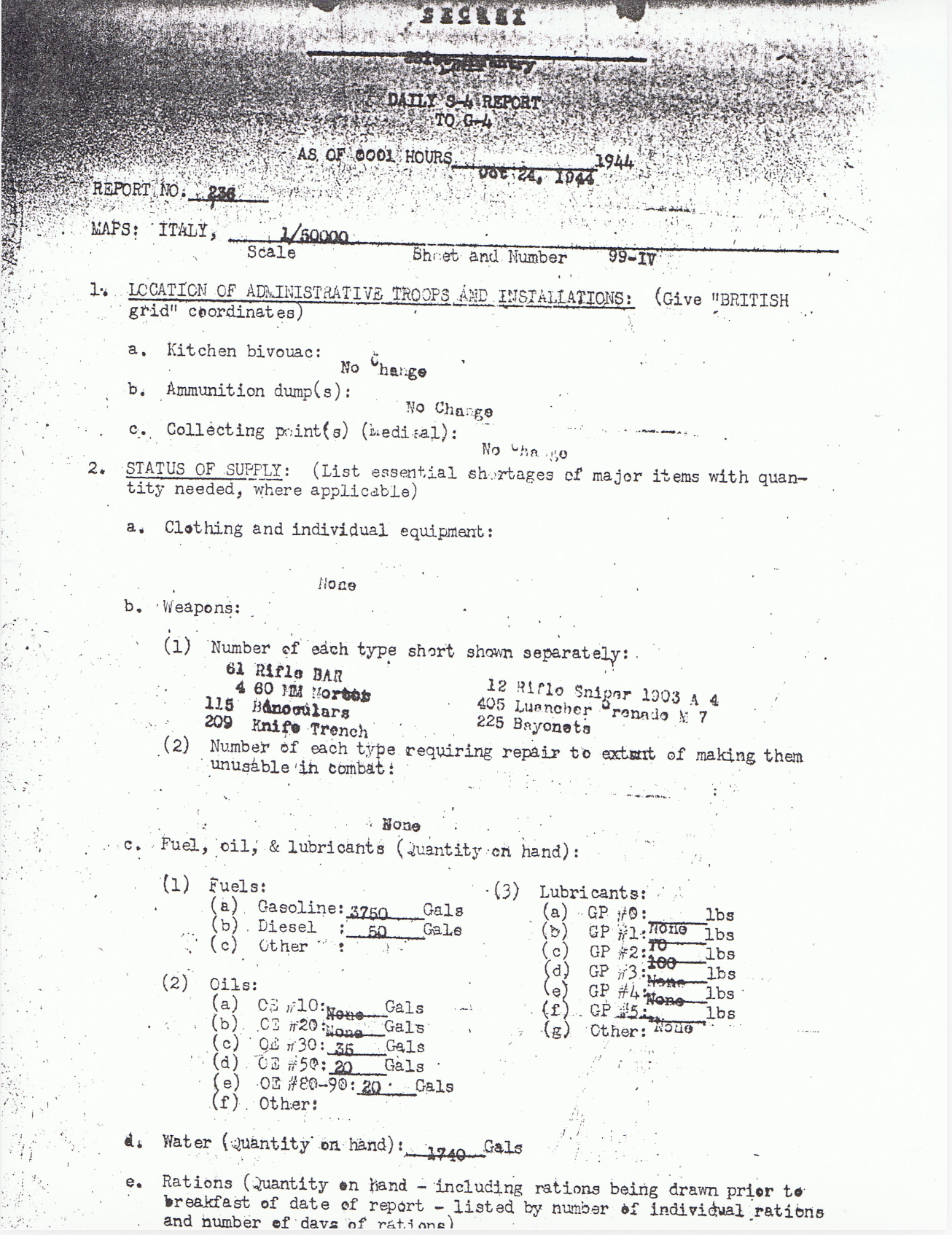
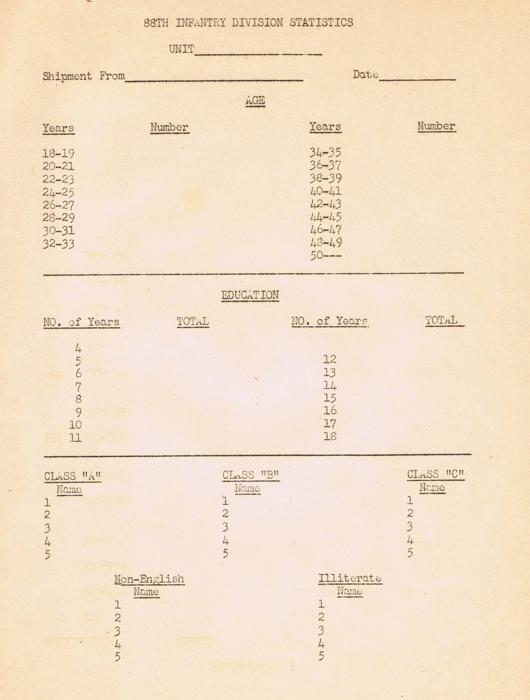
88th Infantry Division Stats Document – A general document to give an idea of what I think might be a shipment of soldiers coming into the unit. The idea is to get a handle on who they are.
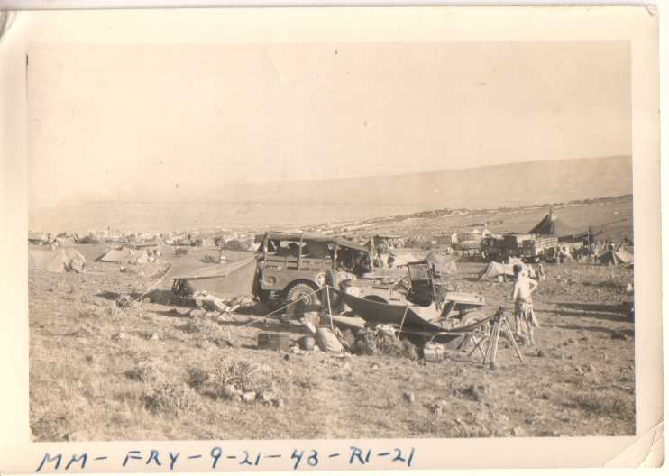
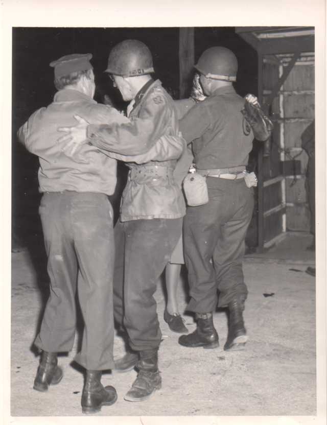
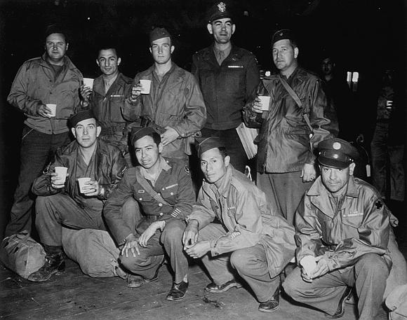
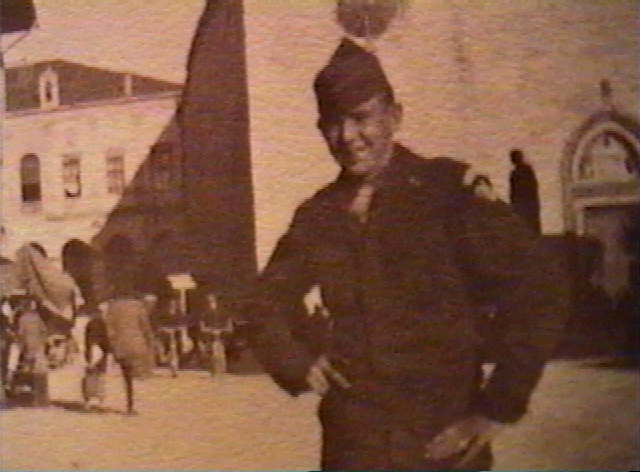
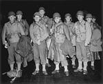
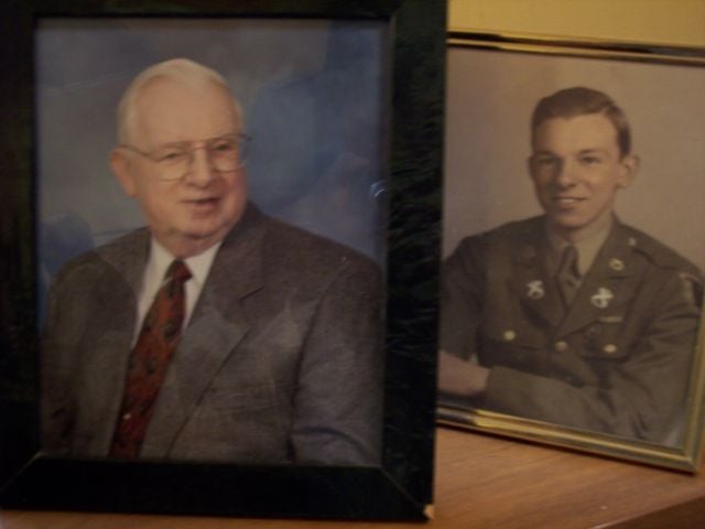
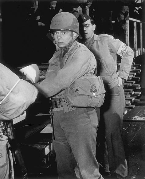
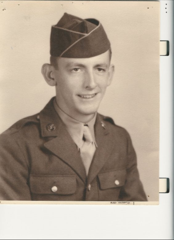
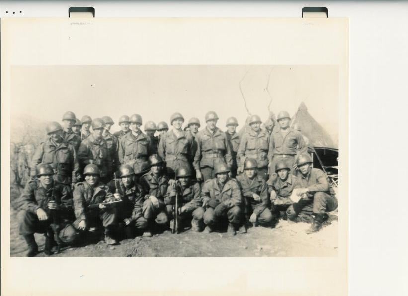
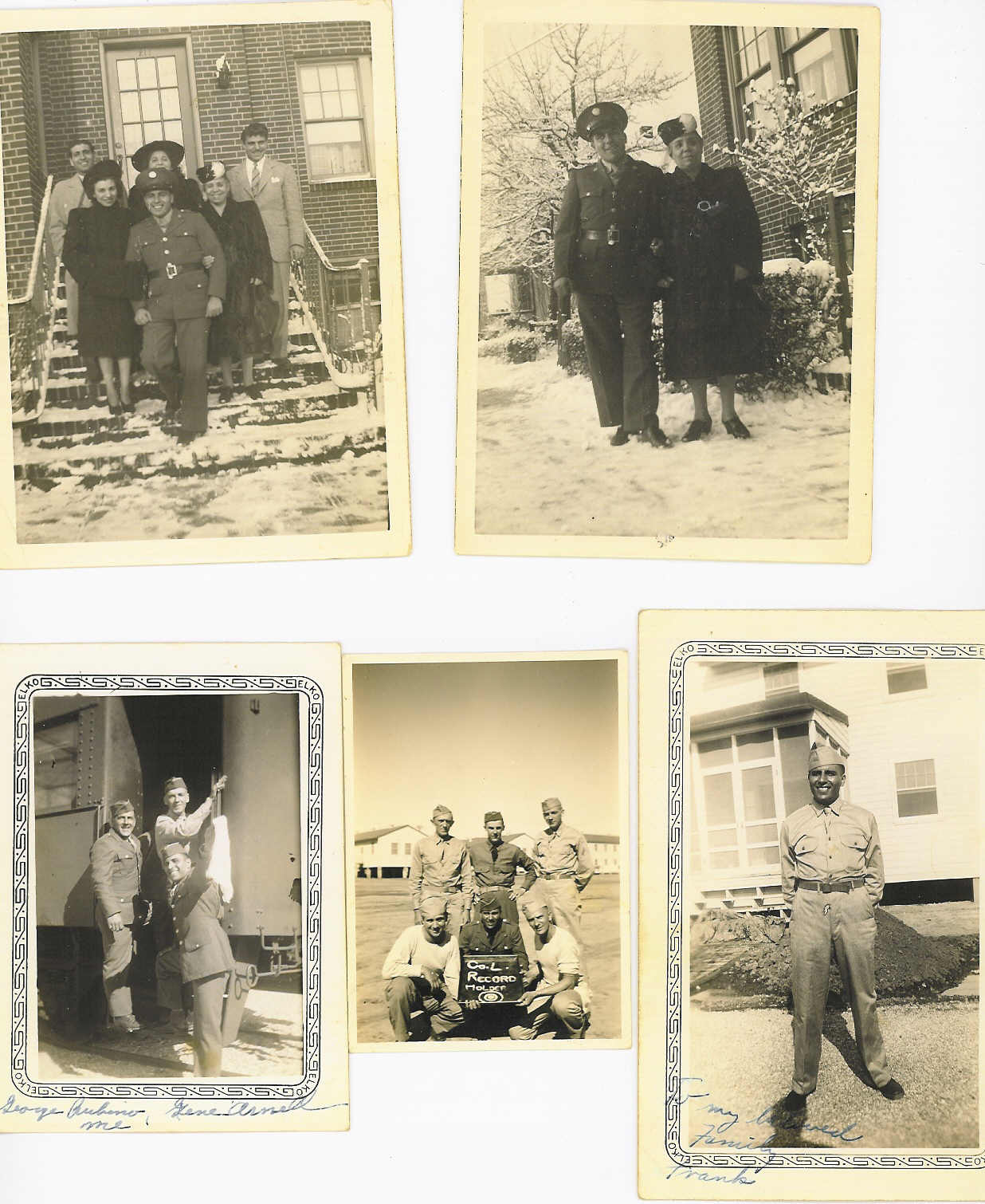
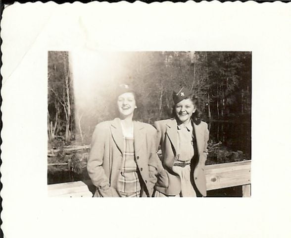
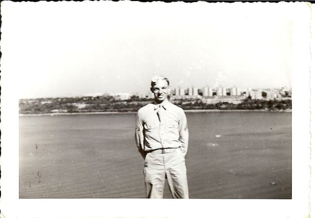
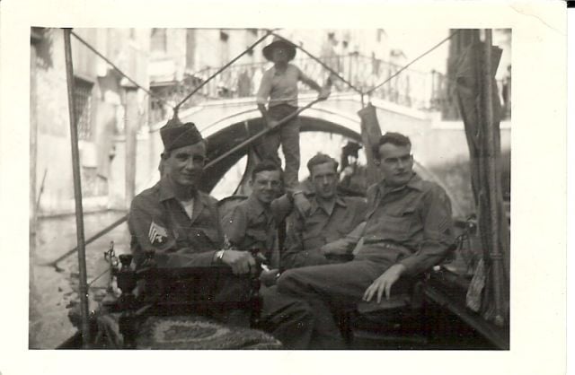
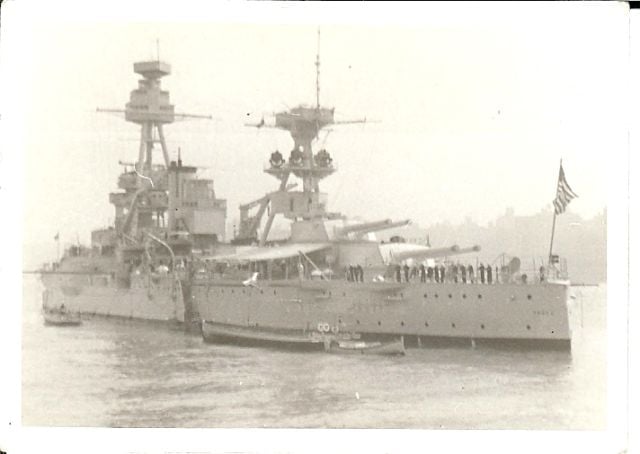
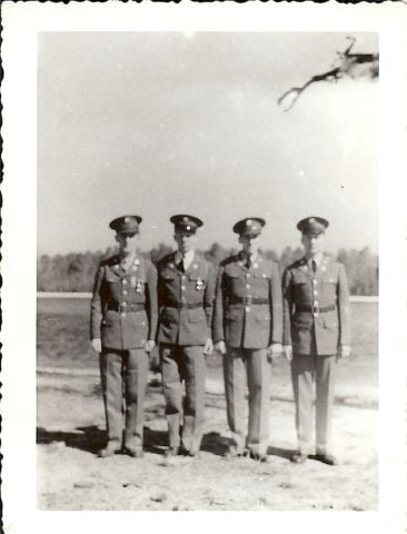
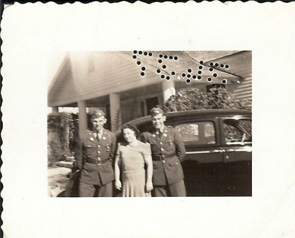
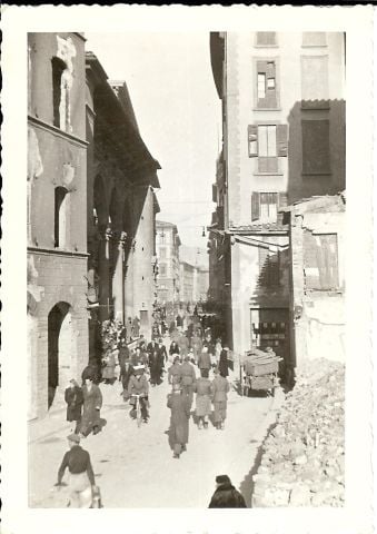
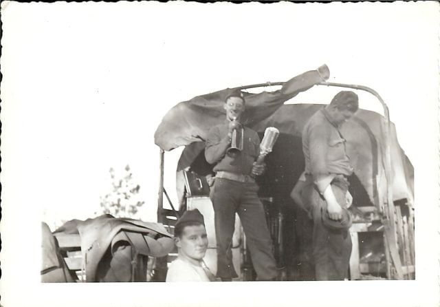
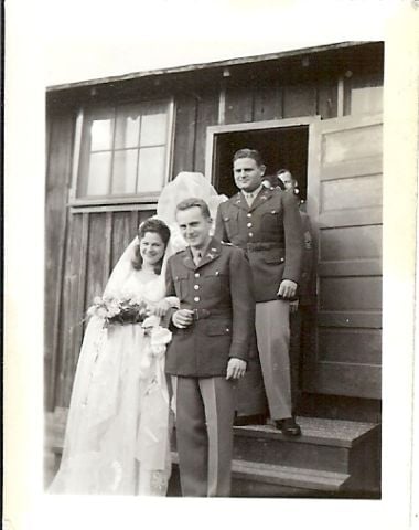
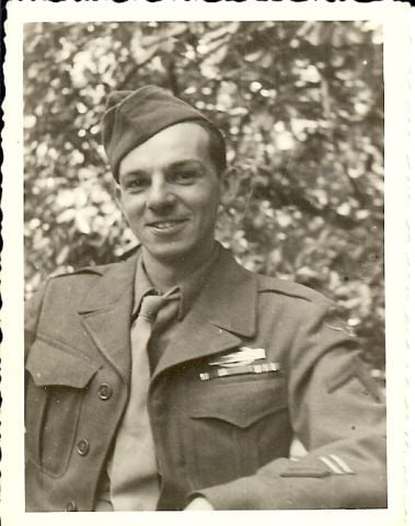
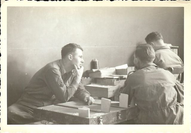
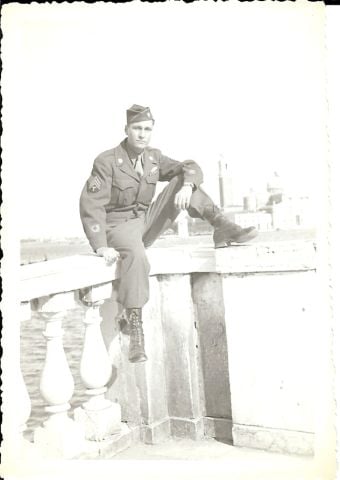
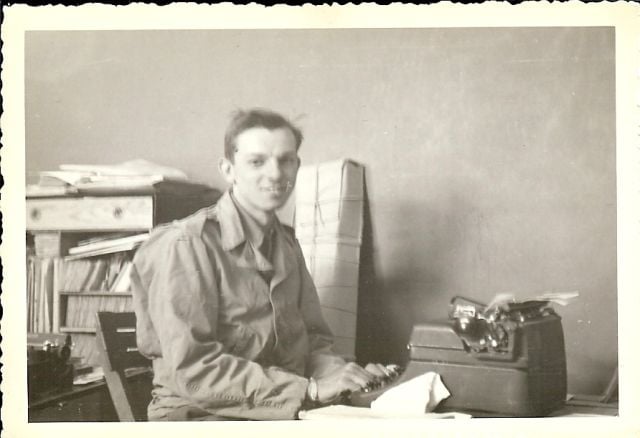
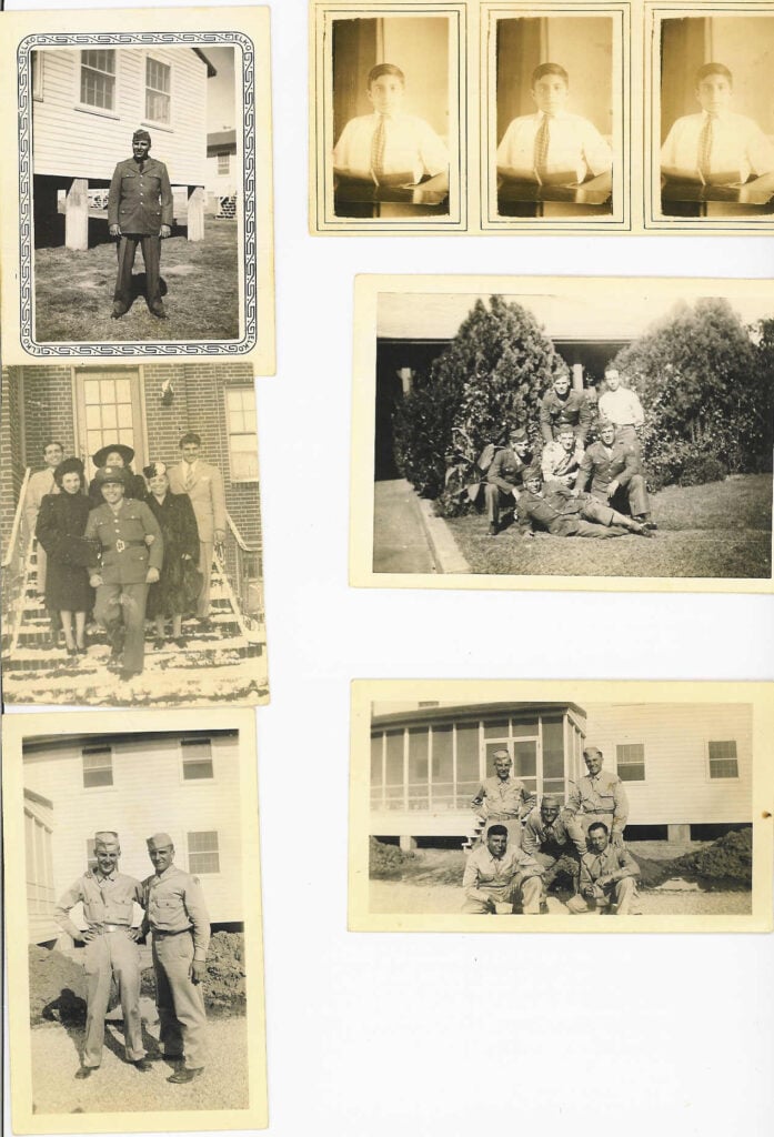
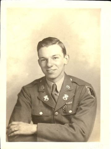
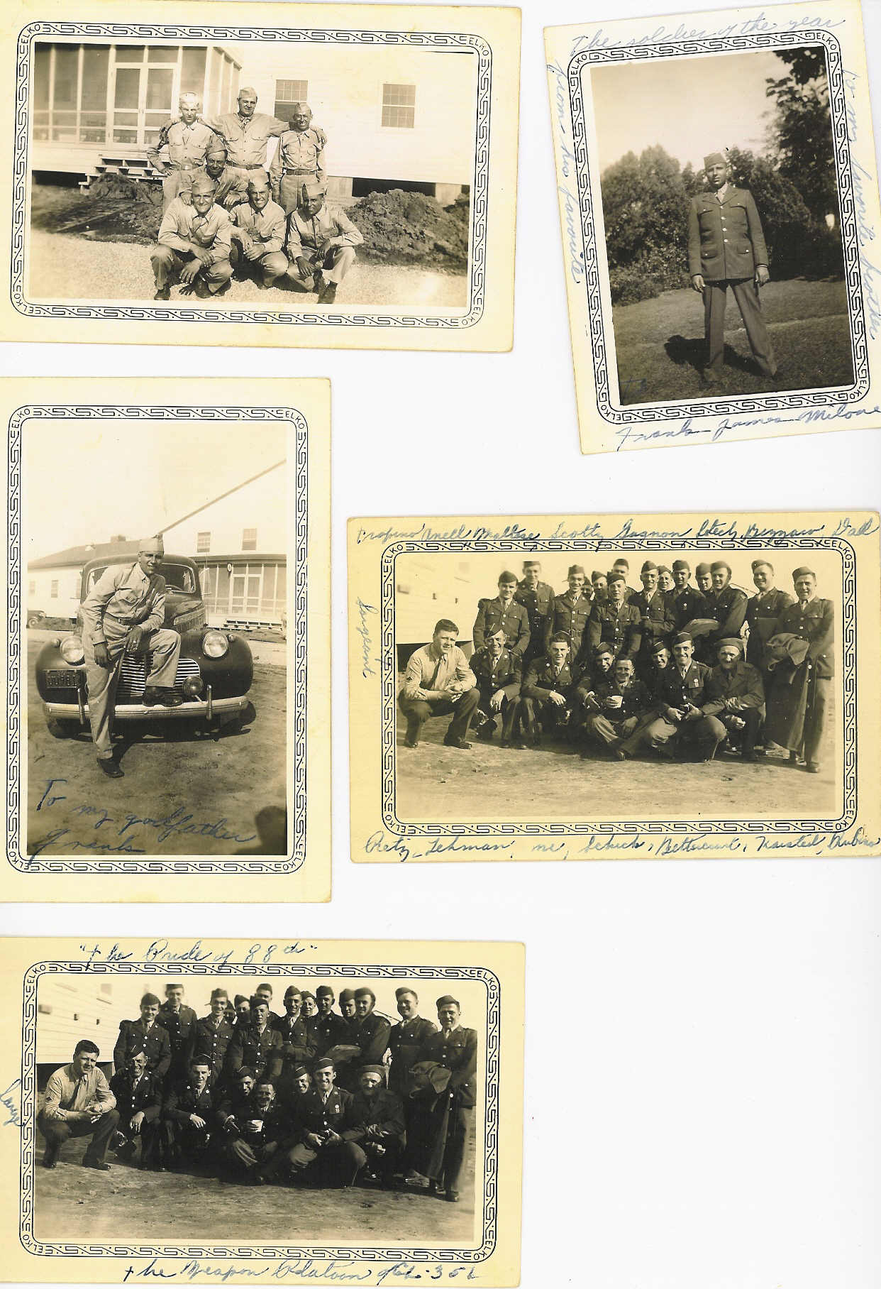
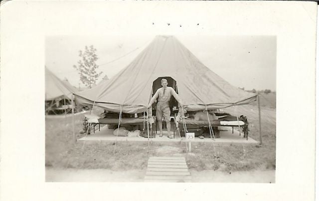
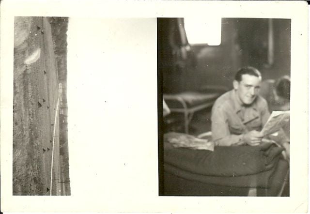
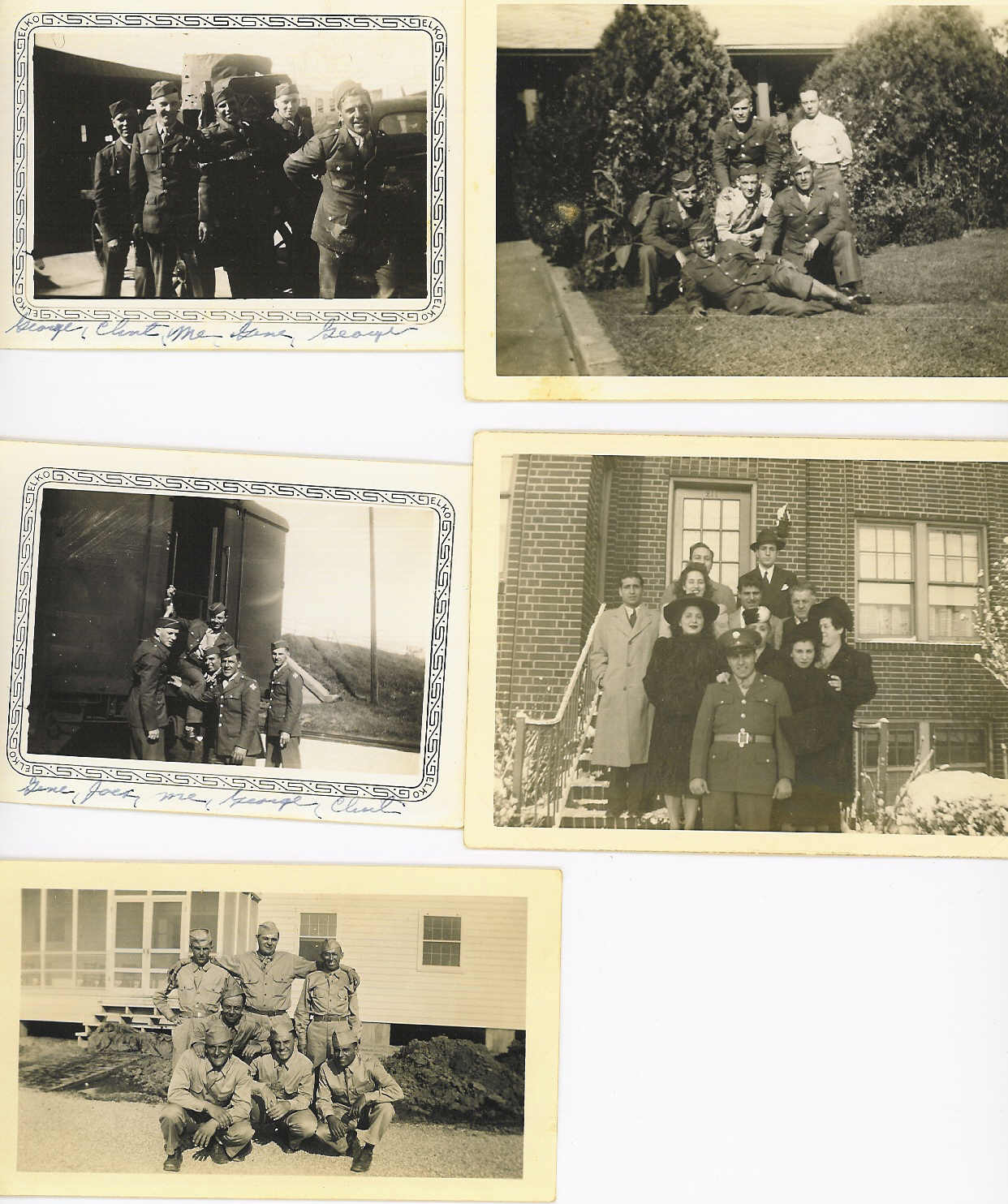
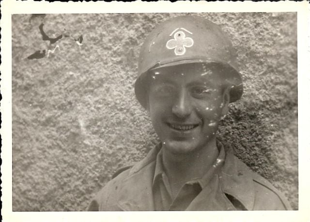
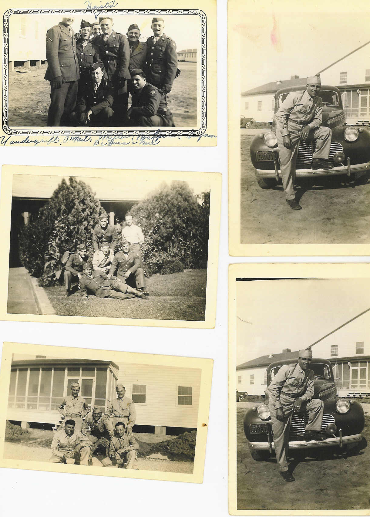
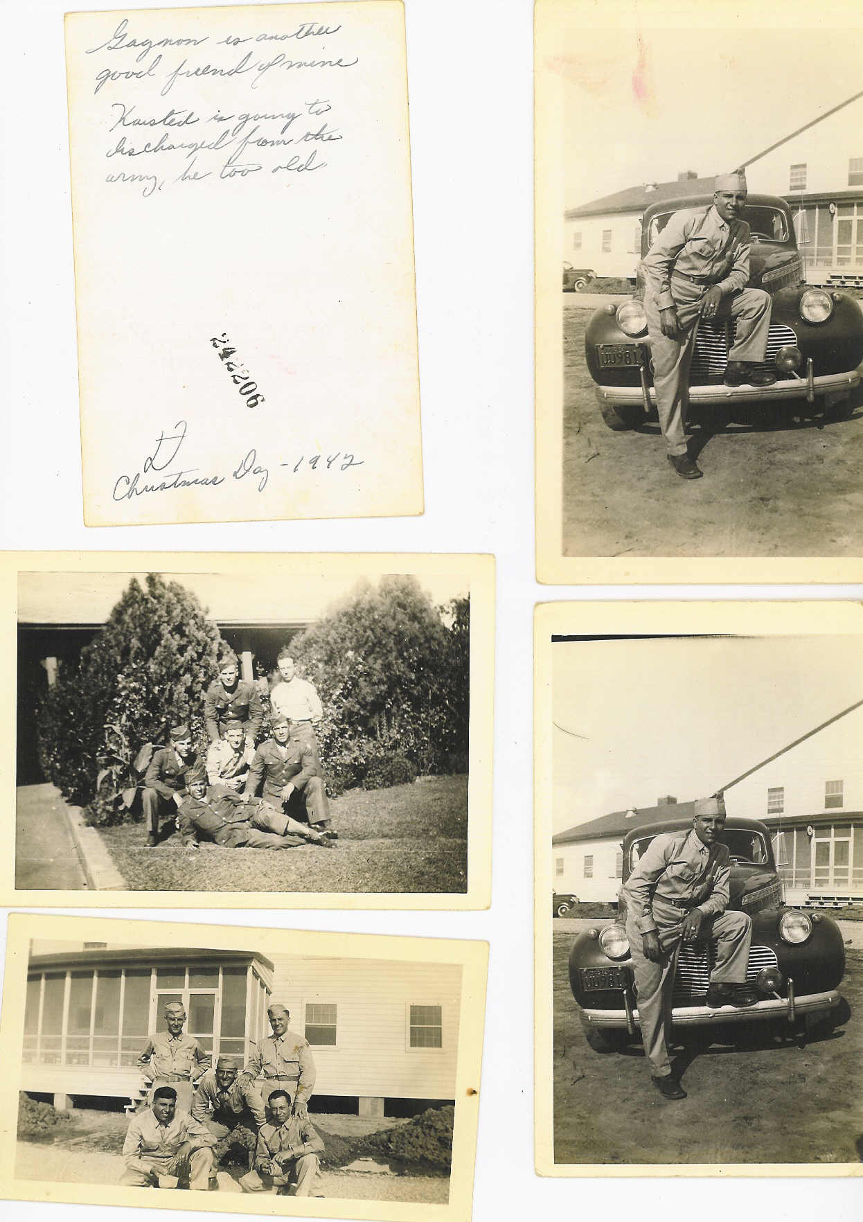
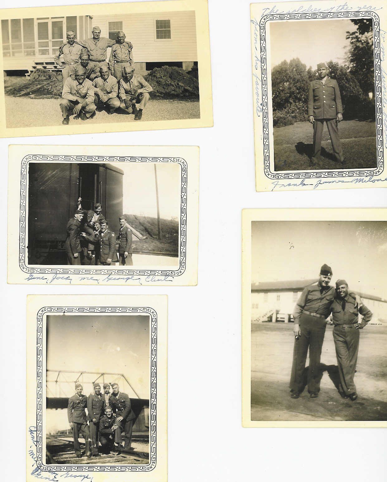
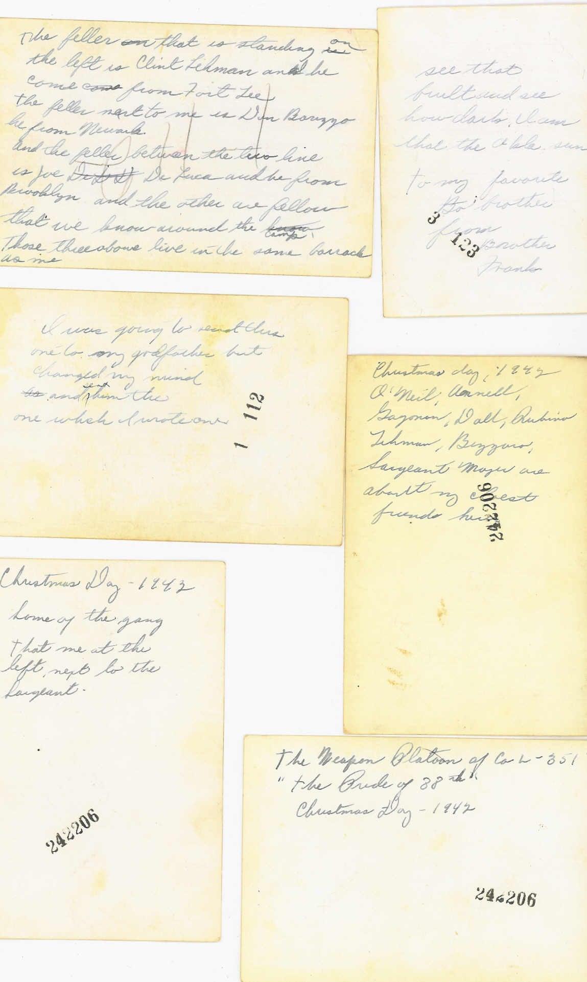
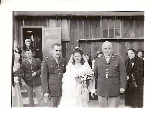
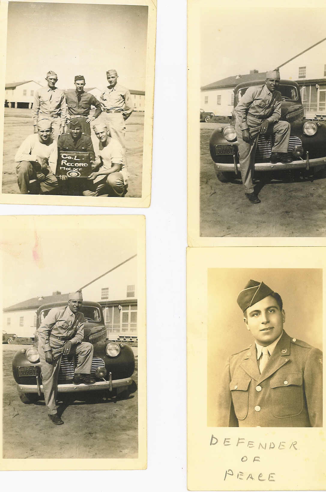
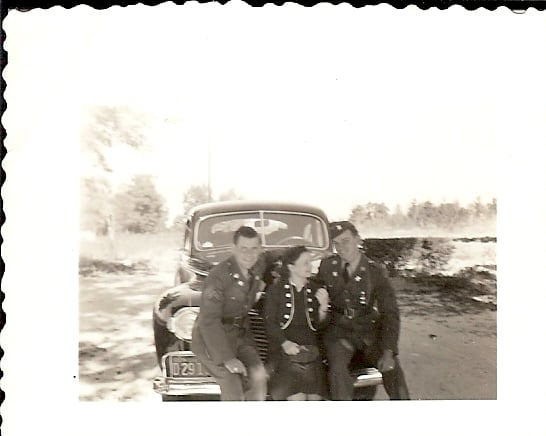
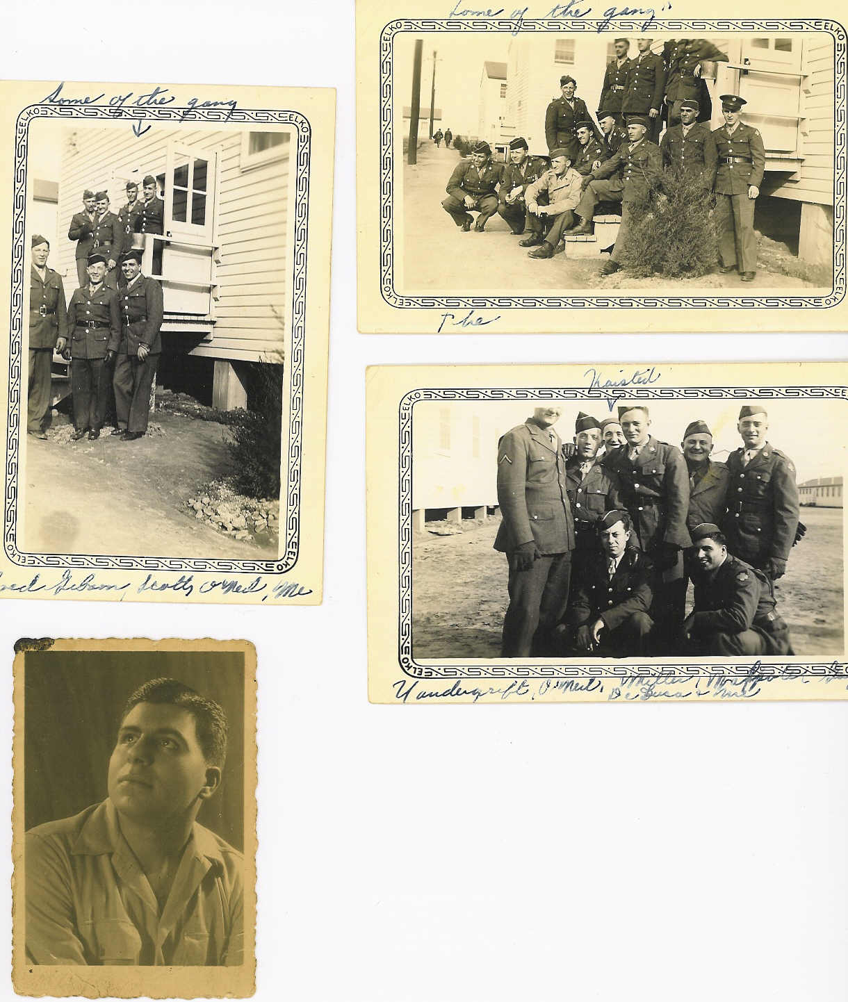
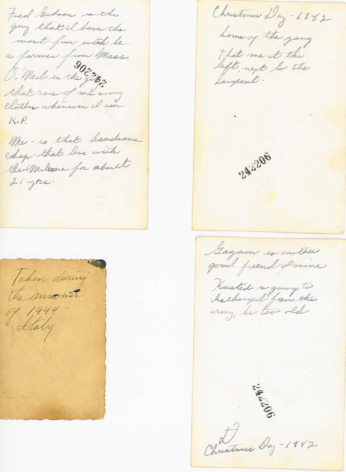
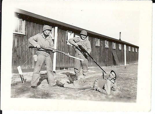
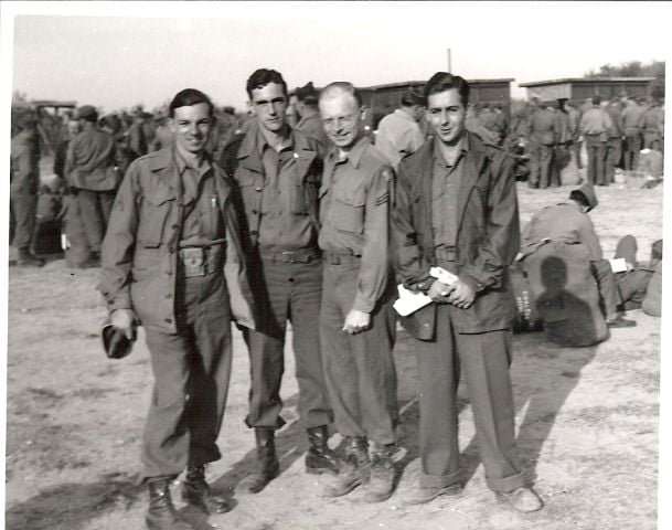
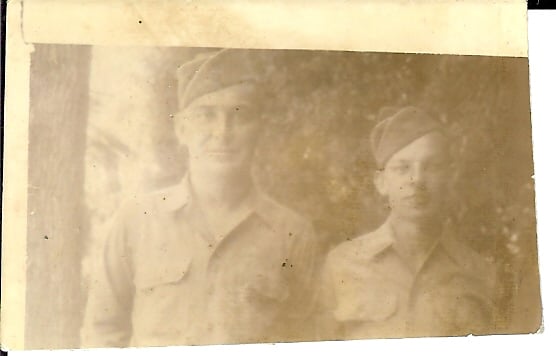
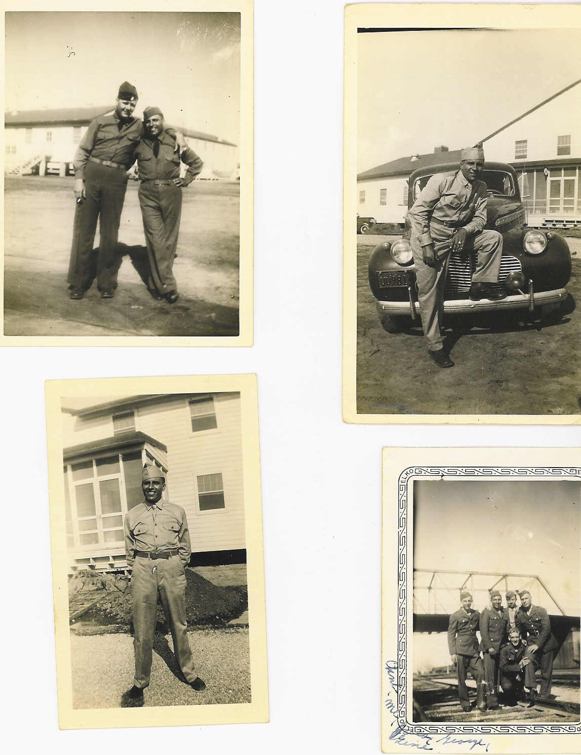
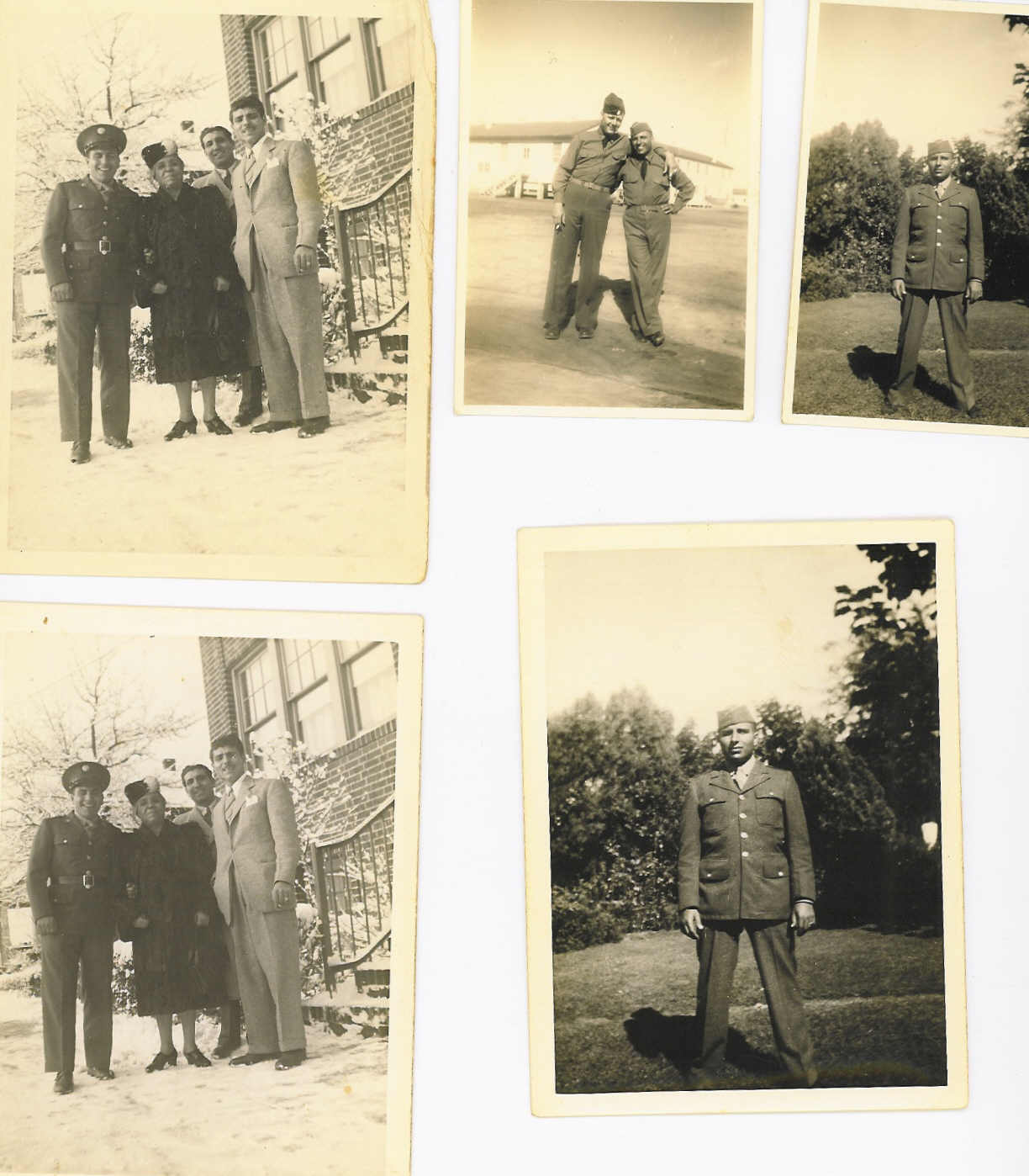
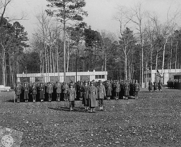
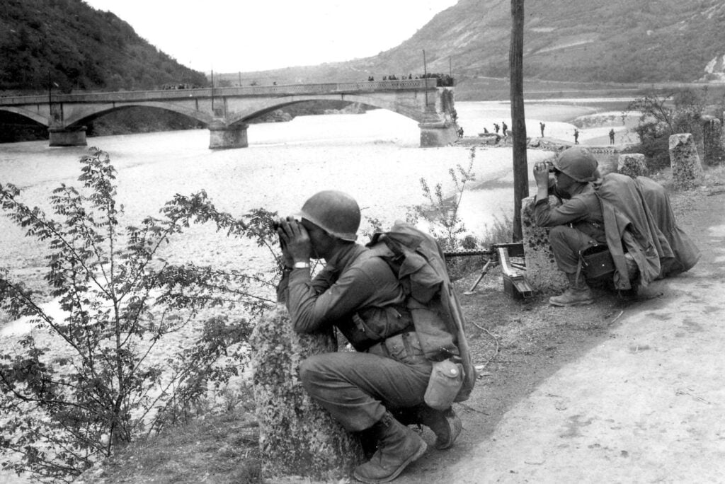
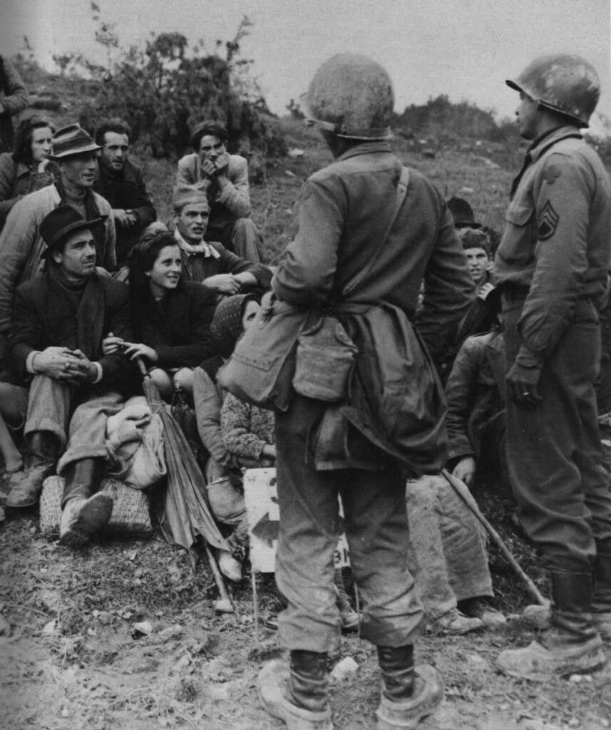
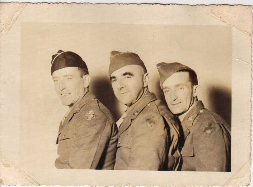
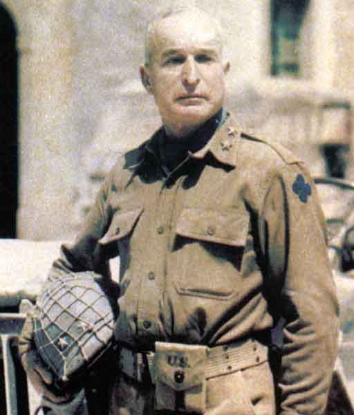
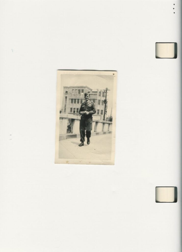
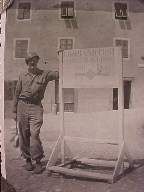
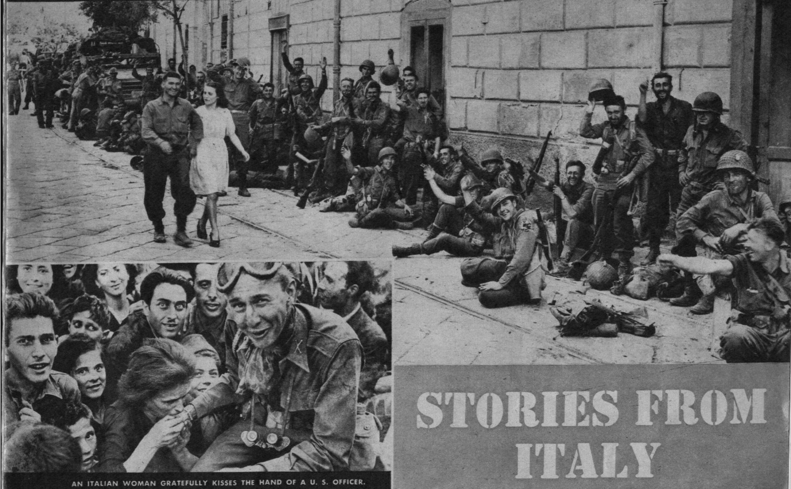
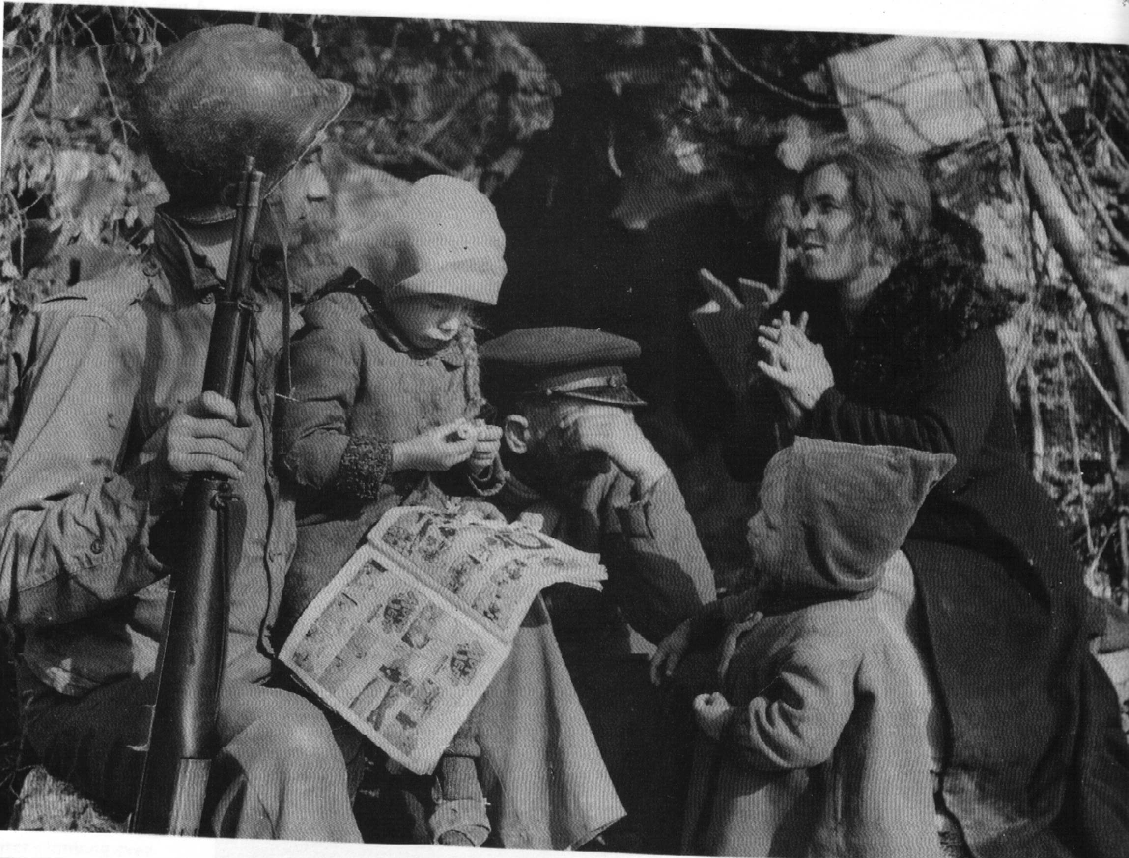
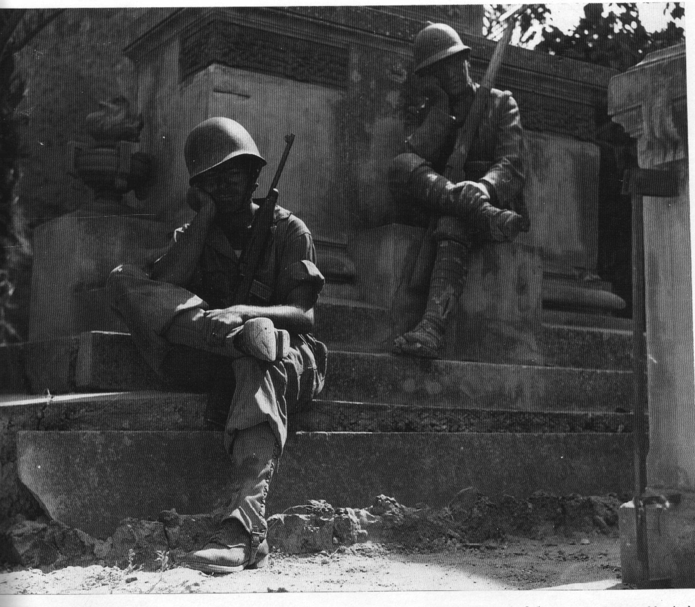
These are just some images I’ve collected over the years. These are all expected to be images of the 88th Veterans or original 88th Infantry Division WW2 era photos.
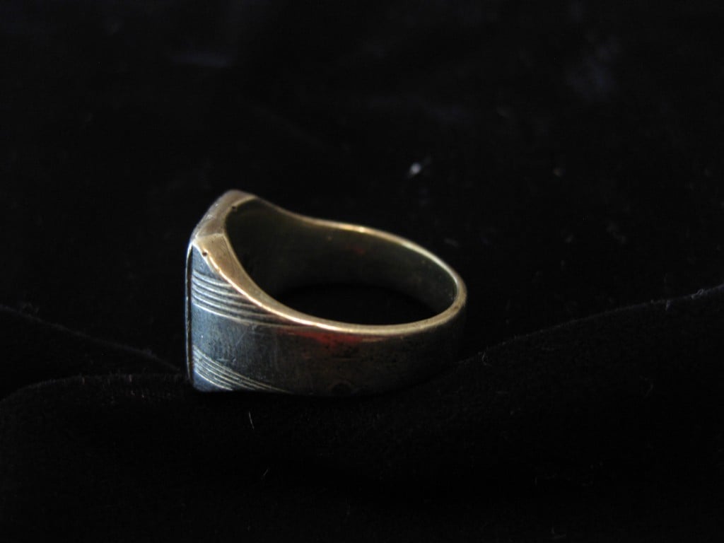
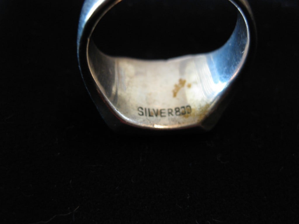
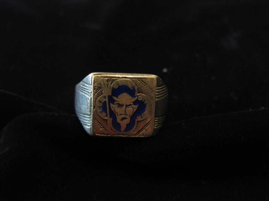
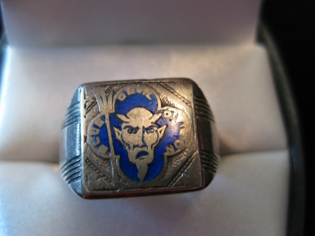
The ring is a vintage WWII 88th Infantry Division, the Blue Devil Division Men’s Ring. Marked on the inside SILVER 800″ and marked around the outside “BLUE DEVIL DIVISION” along the edge of the ring. The ring is worn but not too worn. It is approximately a man’s size 9 1/2-10. The face of the ring is 1/2″ square. and it weighs 12.2 g. Marked 800 Silver, so I’m guessing it was made in Italy during the occupation.
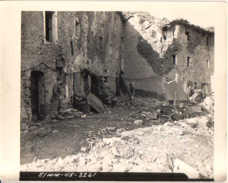
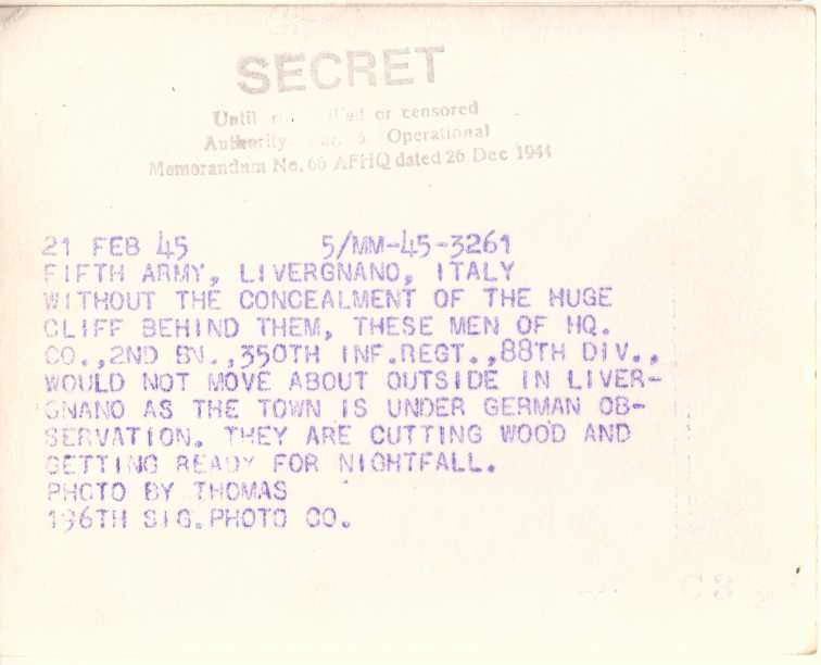
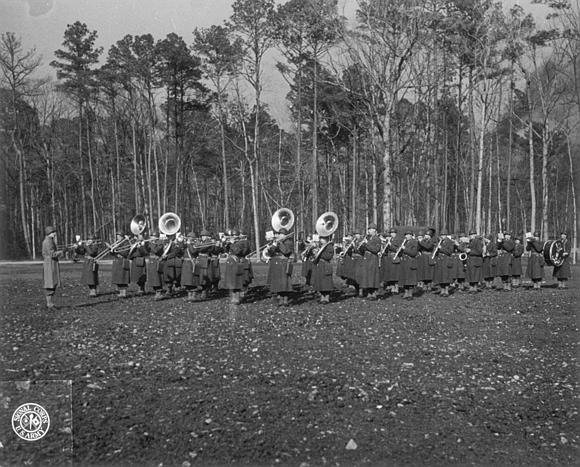
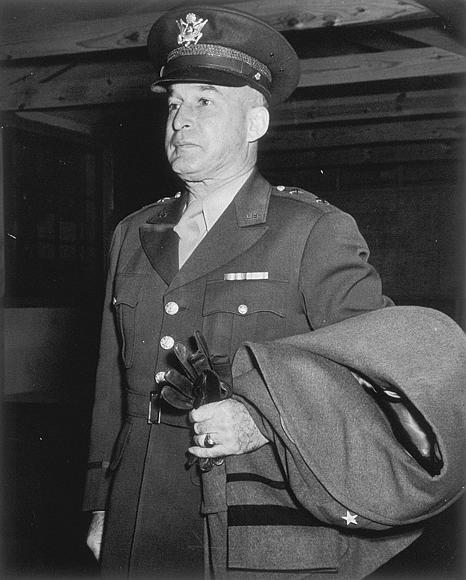
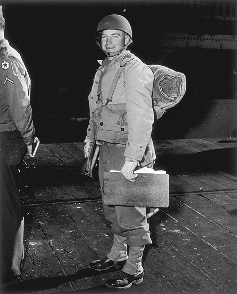
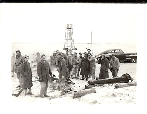
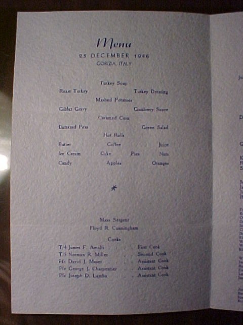
88th Photo Engineer Camp88th Photo Engineer Camp backHQ Co 2nd BN 350th Regiment 88th Division cutting woodHQ Co 2nd BN 350th Regiment 88th Division cutting wood back88th BandMaj Furr, 3rd BN, 351st RegimentBob WellsMaj Gen SloanCpt Glenn Erickson, Company I, 351st Infantry Regiment.Lt Col Eugene Cowles?Maj Gen Sloan88th ID Monterumici Italy 1945Three men in a Nov 13, 1943, Johnson Sayers Studio, Briggs, Okla., group shot. A 3-1/2 x 5 Inch Photograph.Maj General SloanBob Wells, an 88th Veteran who served in Korea. Picture taken in Korea88th ID Mass Castleforte Italy 194488th Christmas 1946 menu
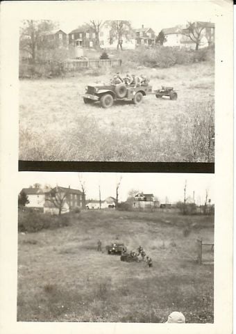
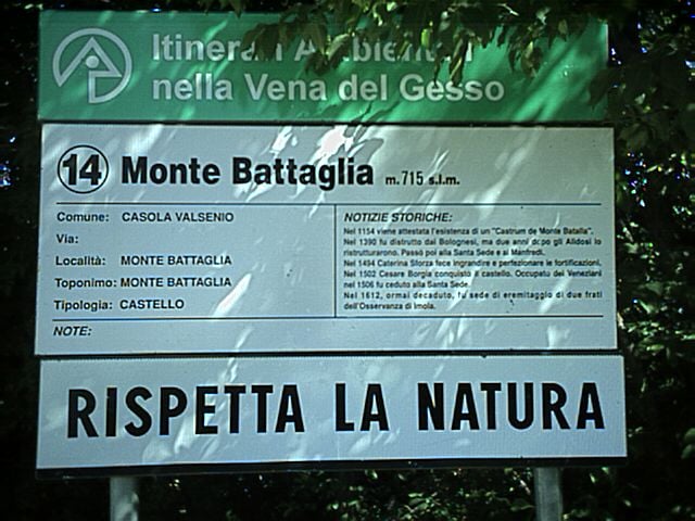
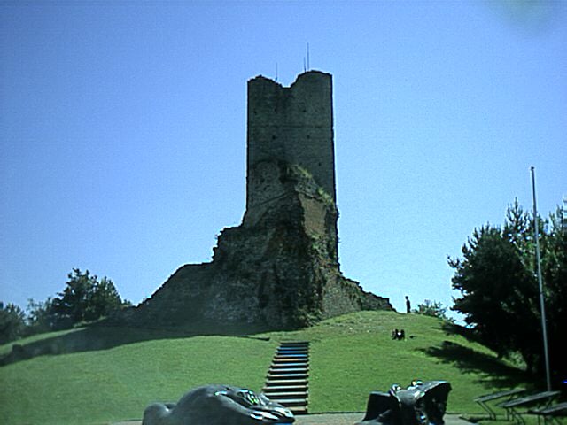
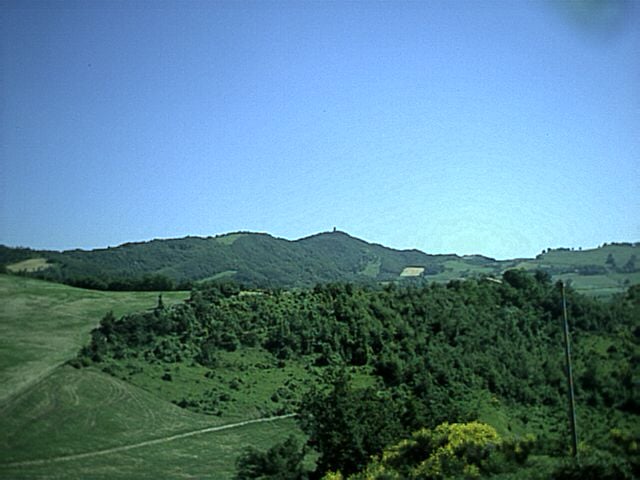
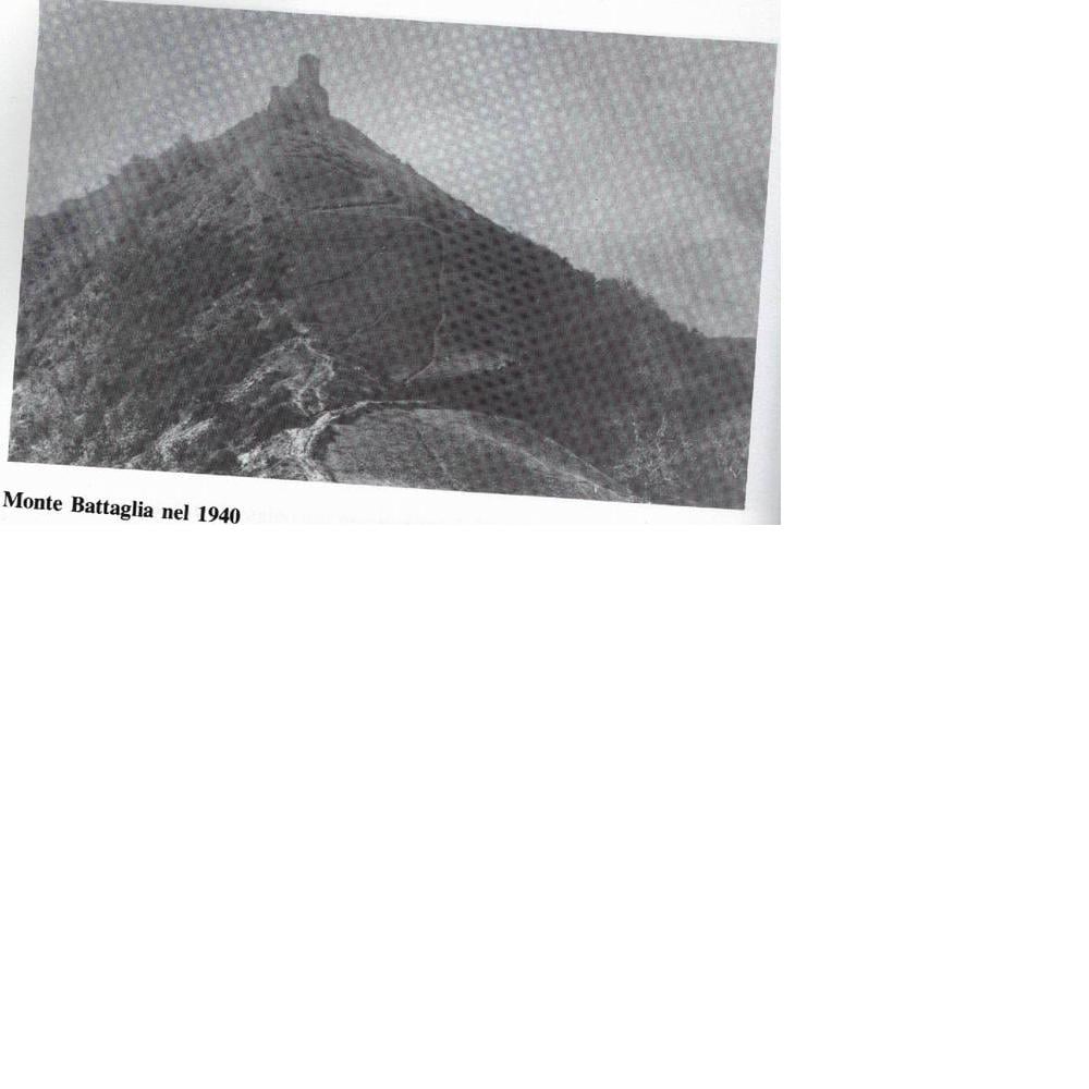
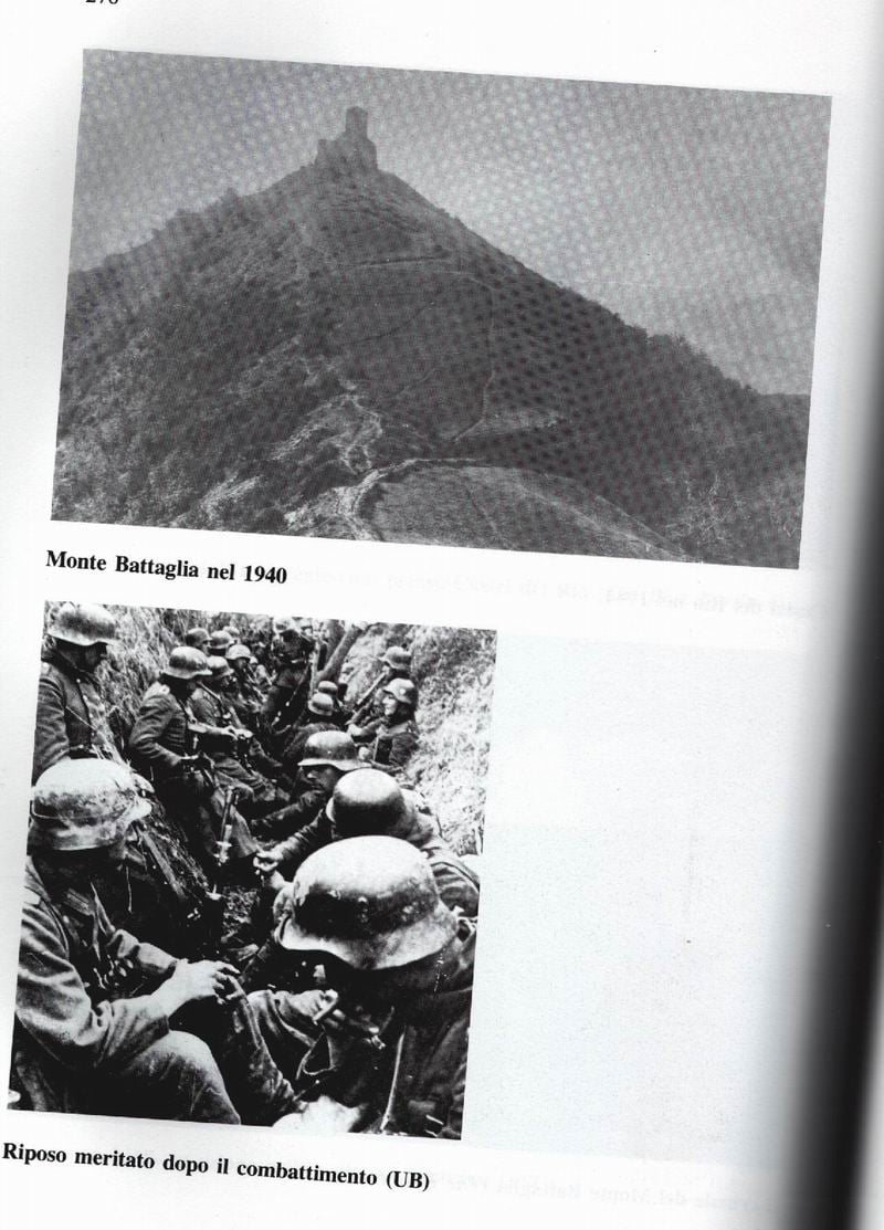
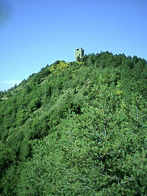
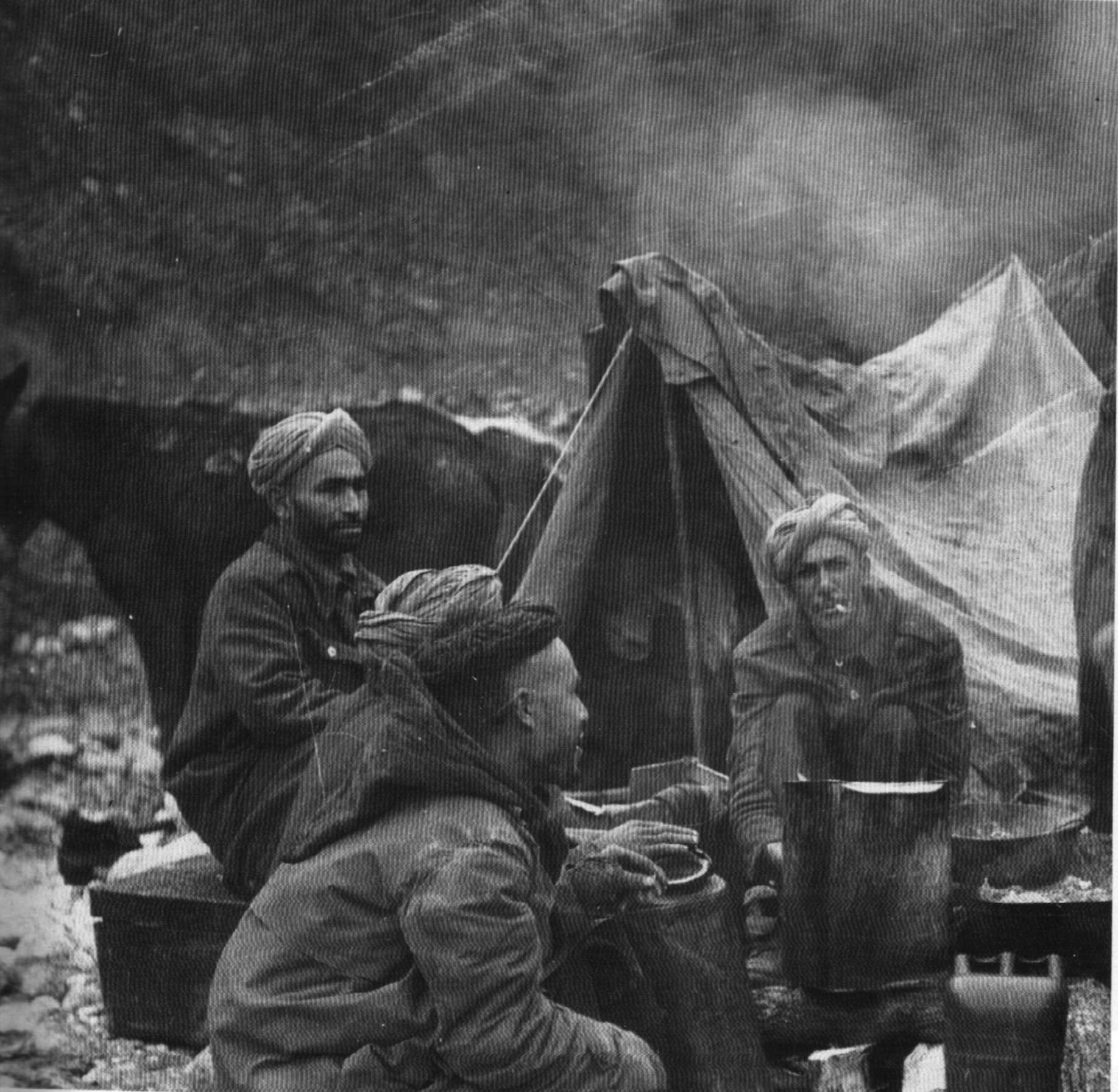
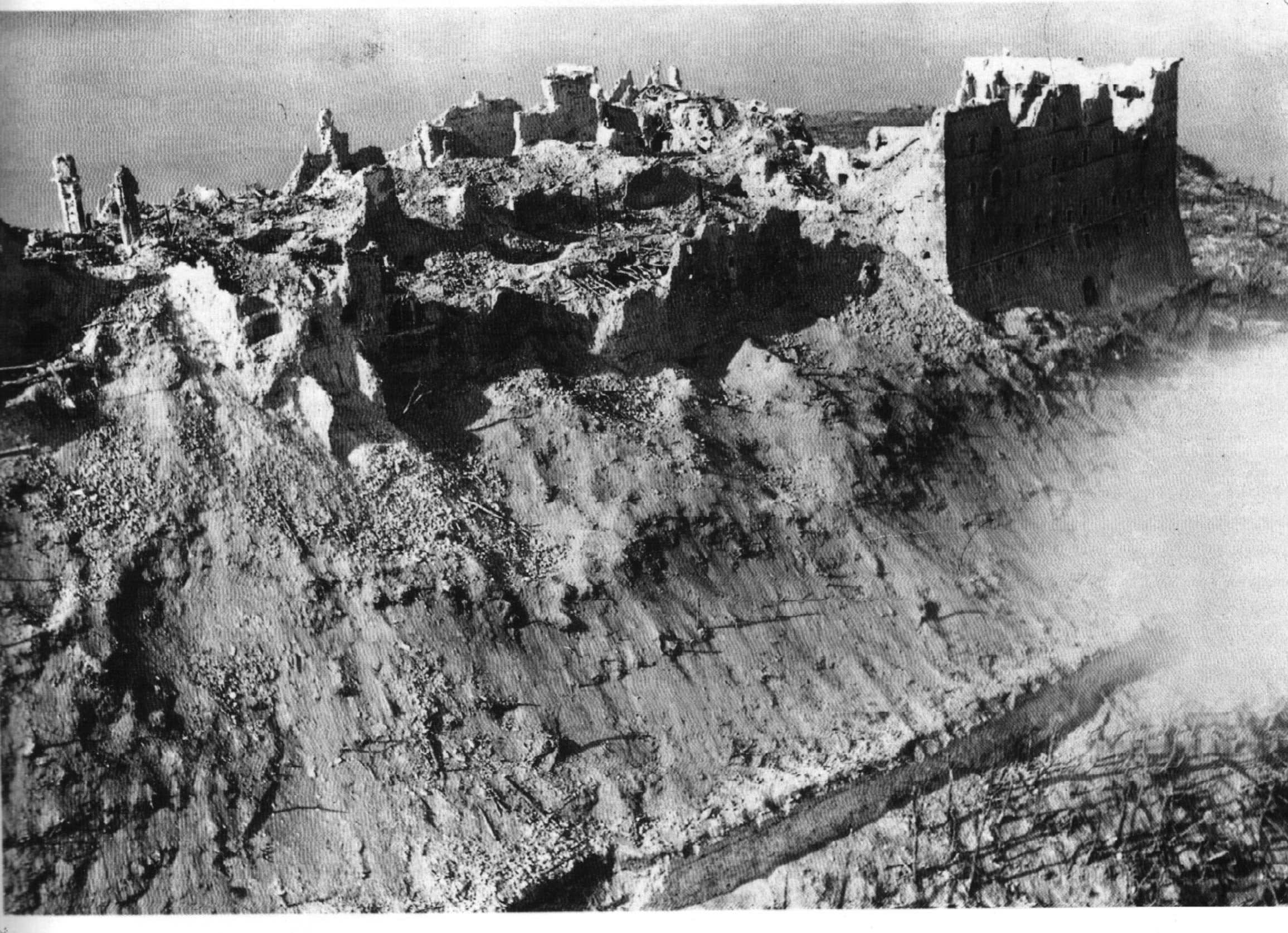
Battle Mountain Photos
The Battle Mountain photos were taken by a fellow history buff in the early 2000s.
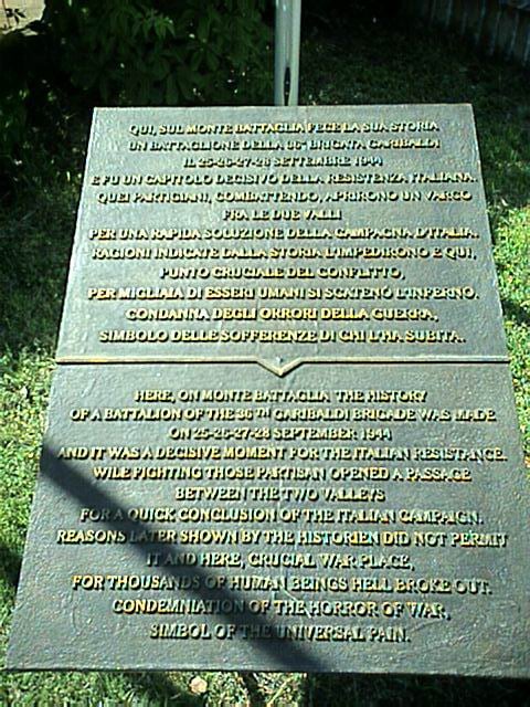
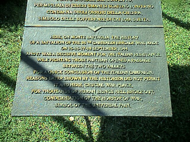
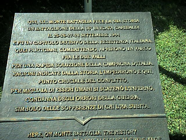
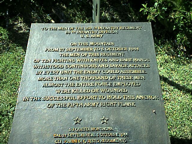
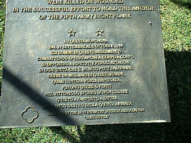
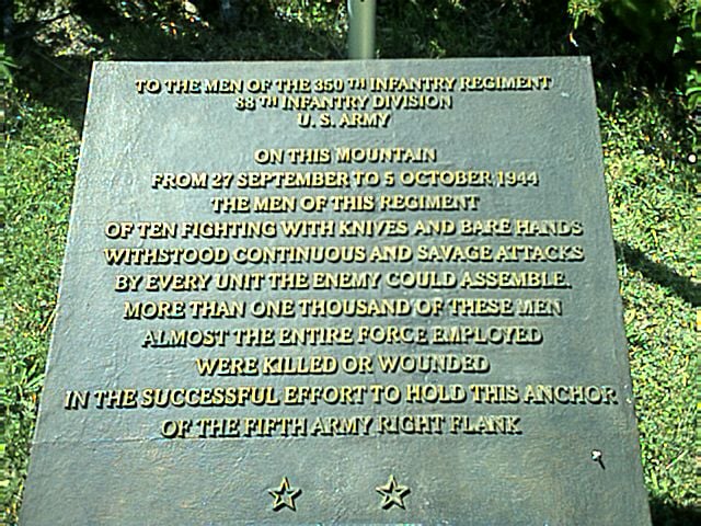
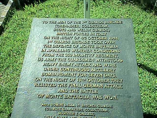
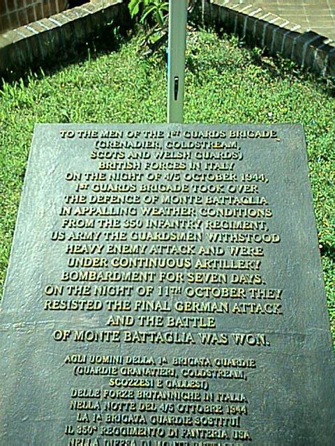
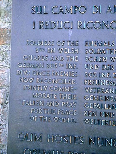
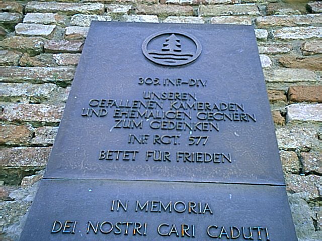
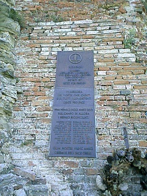
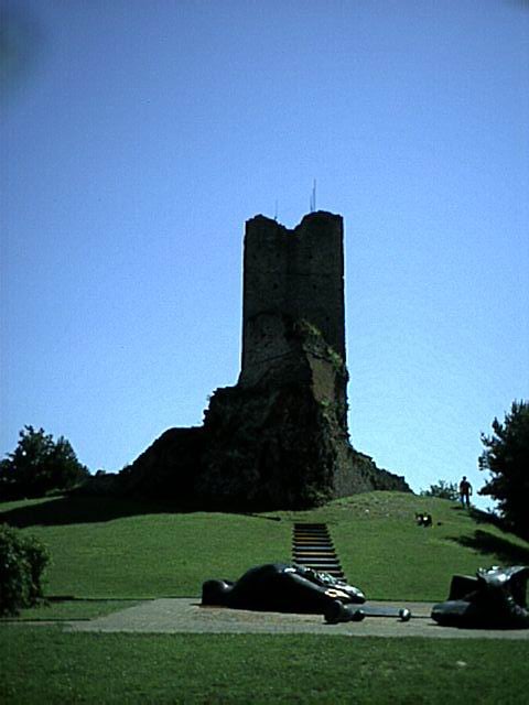
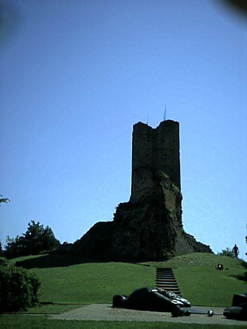
Monuments
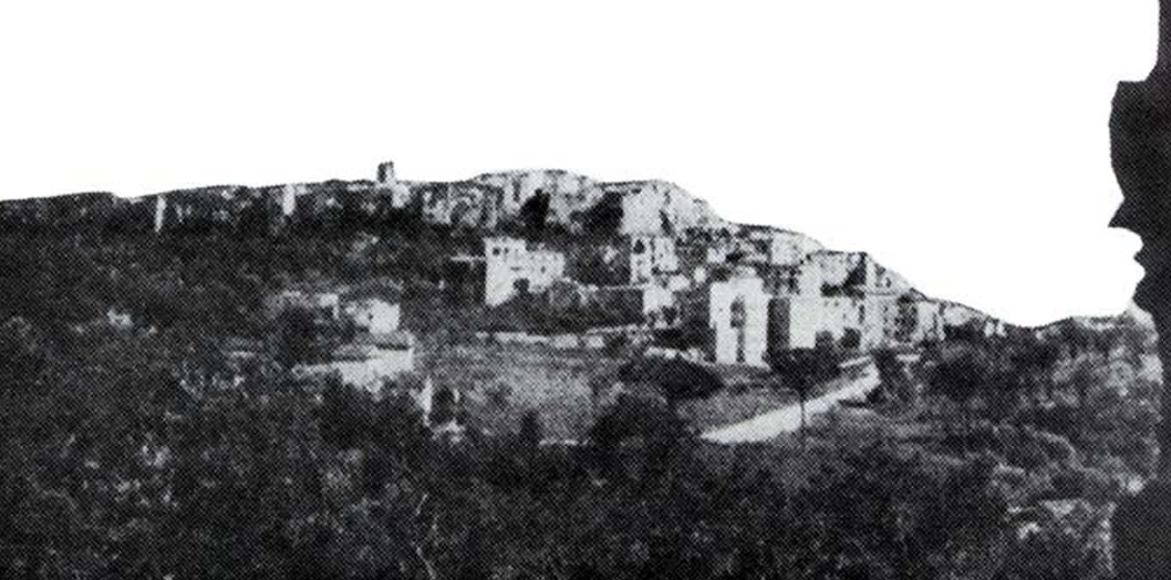
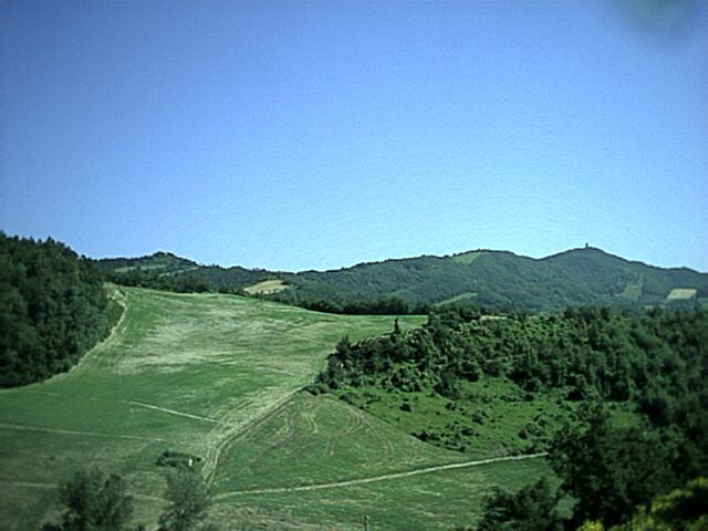
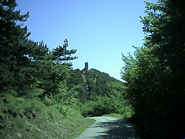
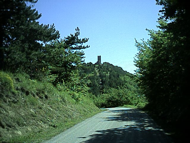
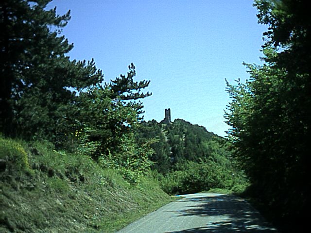
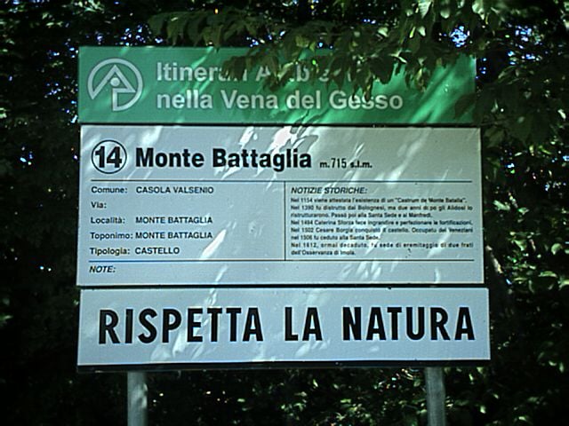
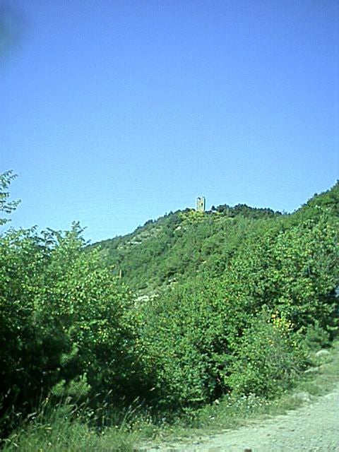
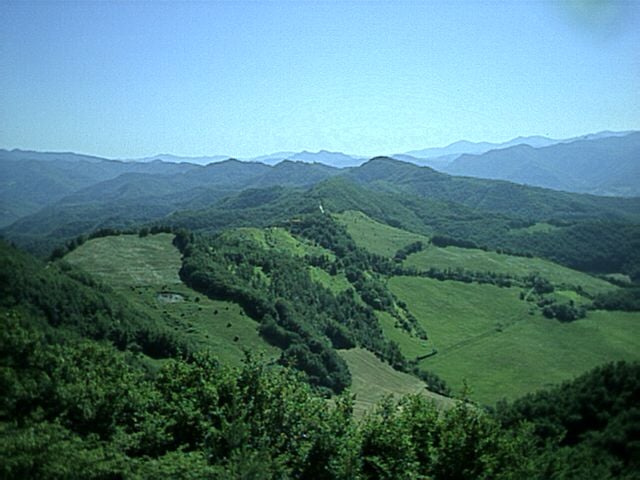
Battle Mountain as shown from the perspective of the German lines
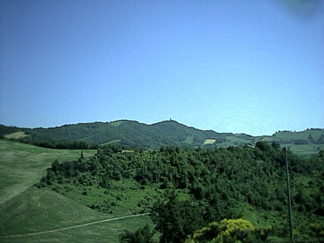
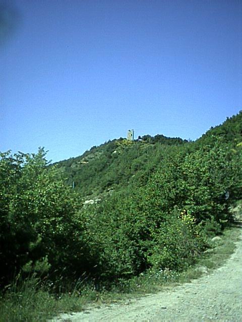
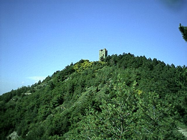
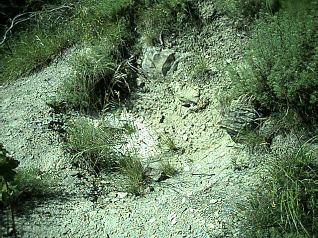
Street used by German to attack mount
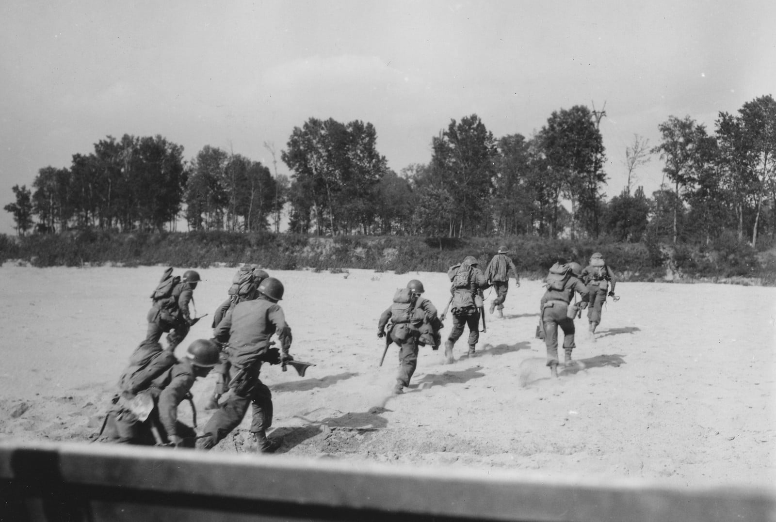
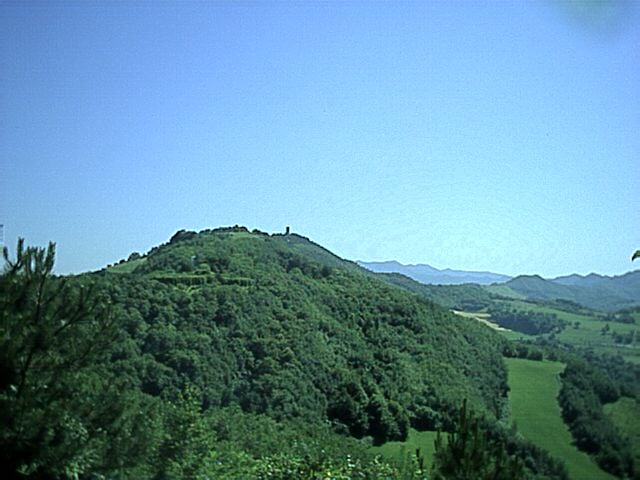
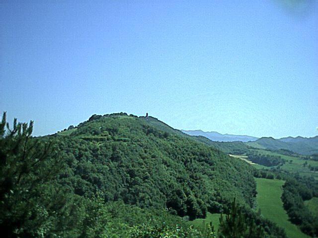
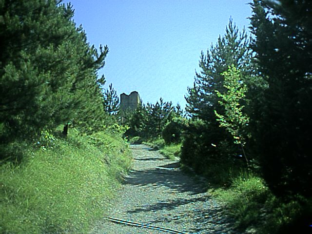
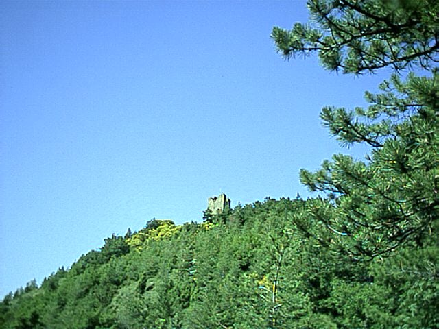
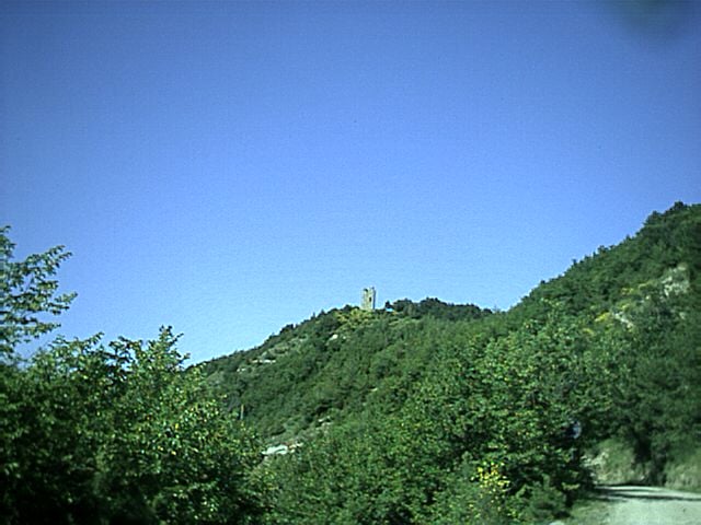
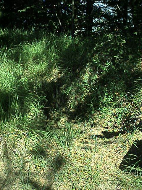
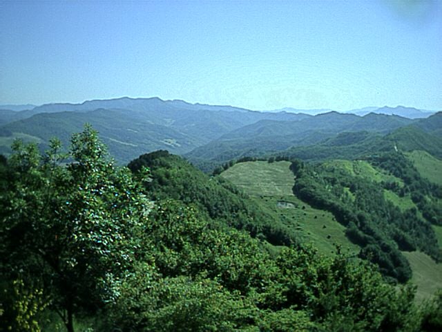
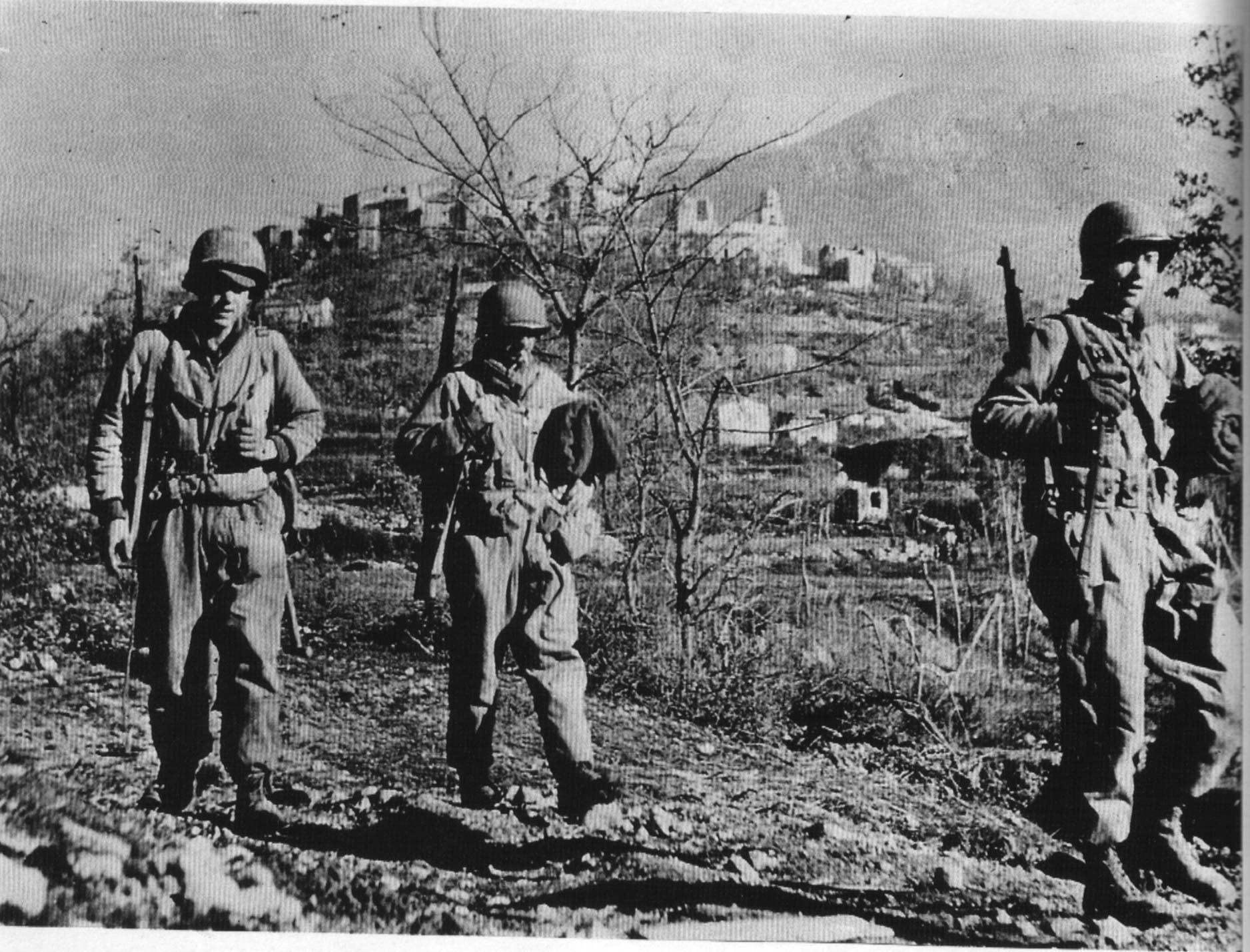
Battle Mountain from the US lines as they approach it
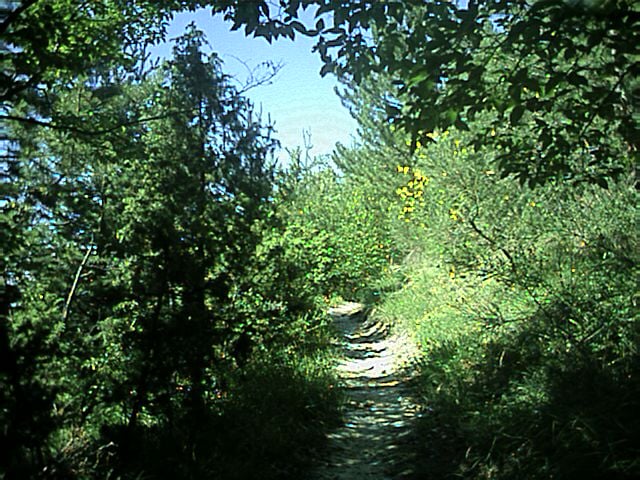
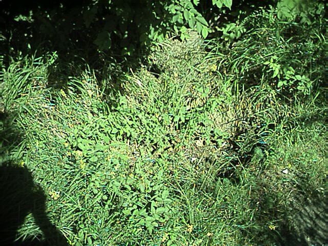
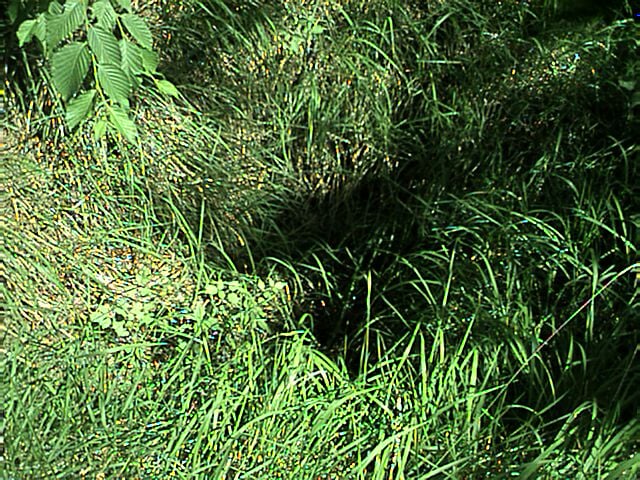
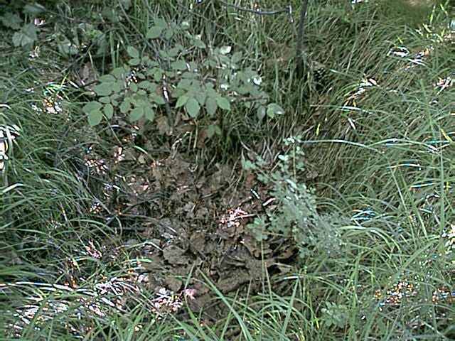
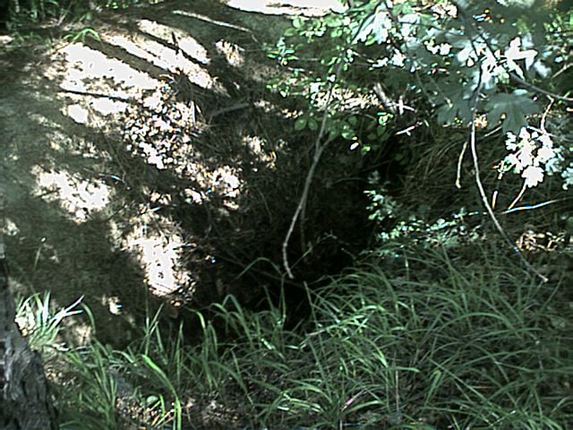
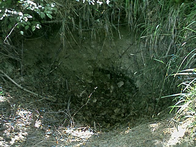
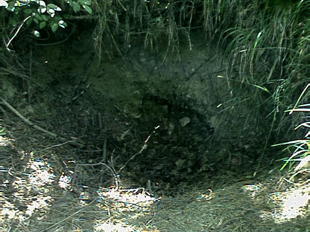
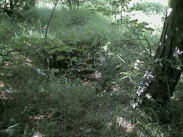
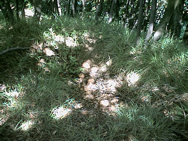
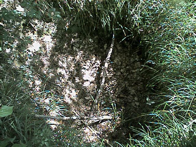
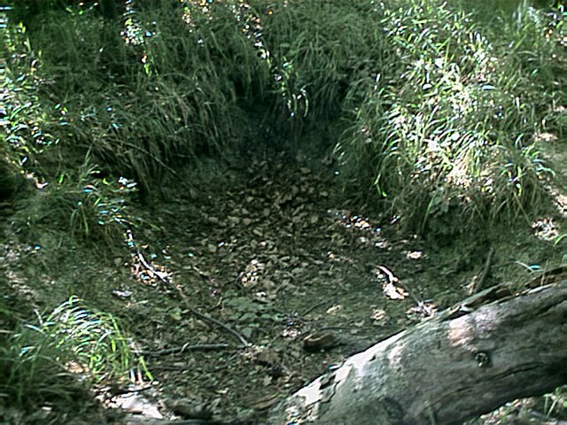
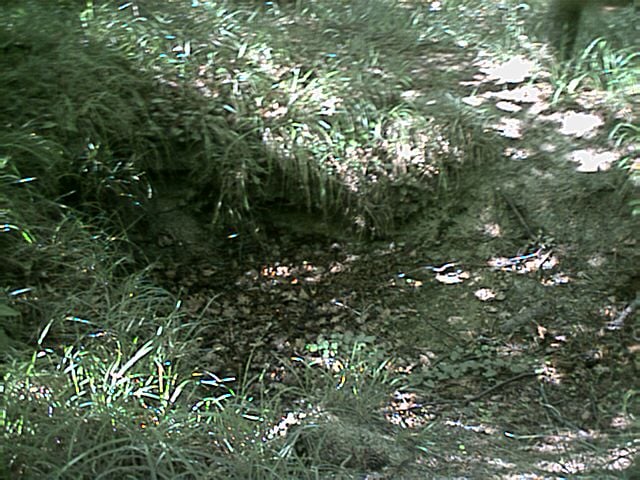
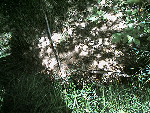
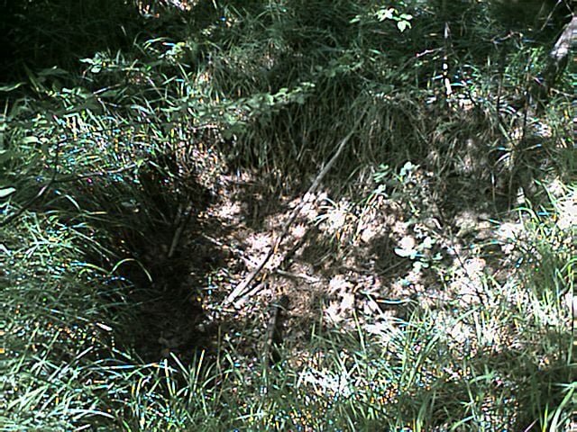
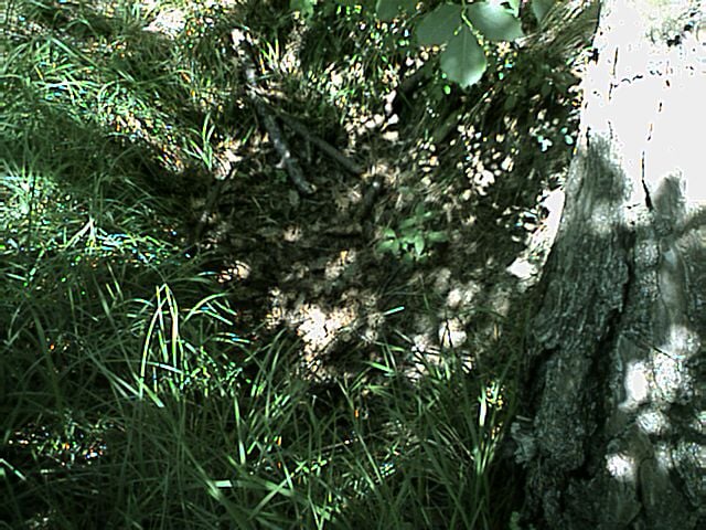
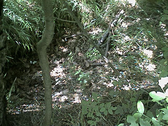
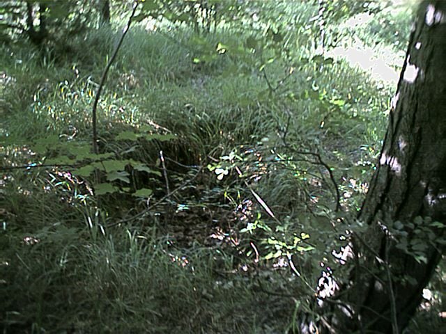
Trenches and Foxholes on Battle Mountain
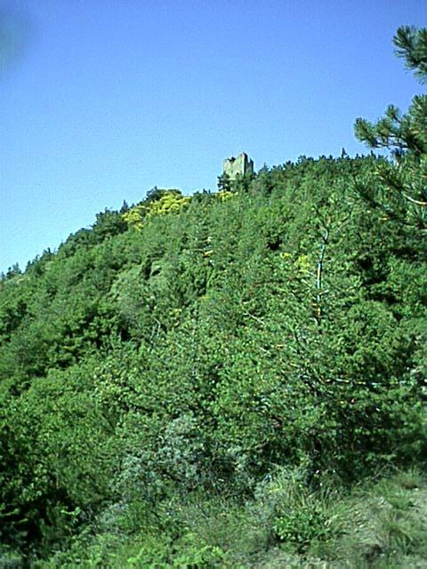
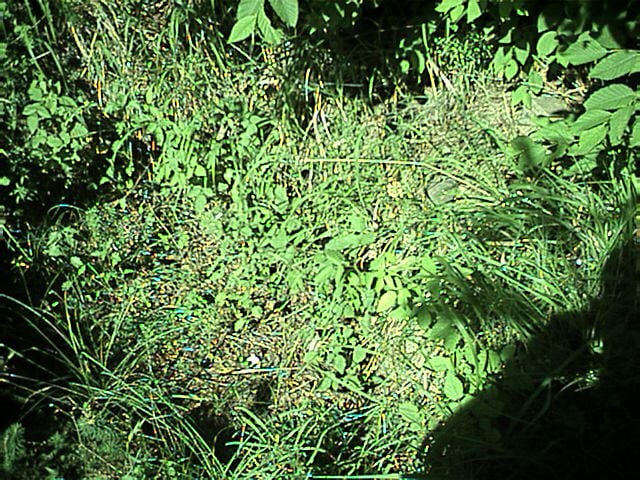
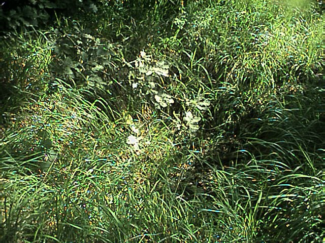
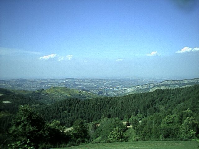
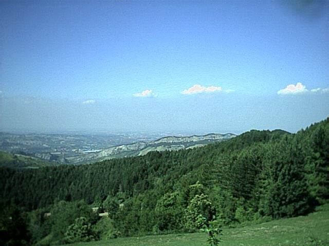
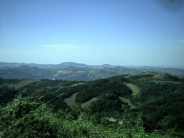
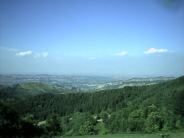
View from Battle Mountain
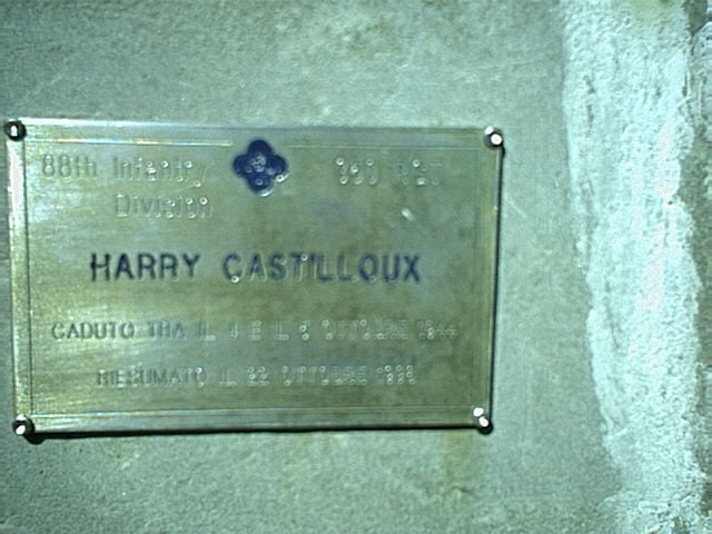
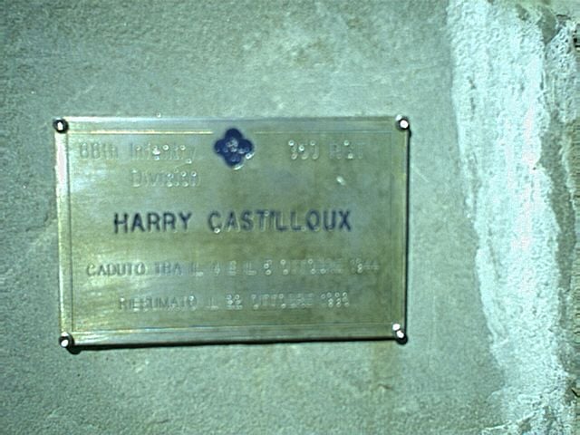
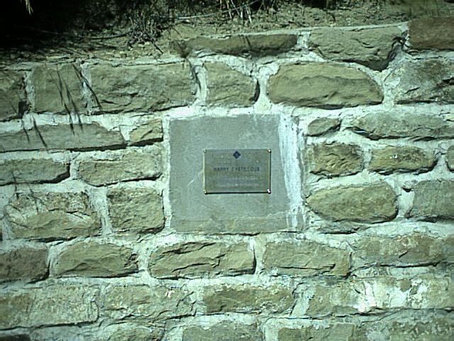
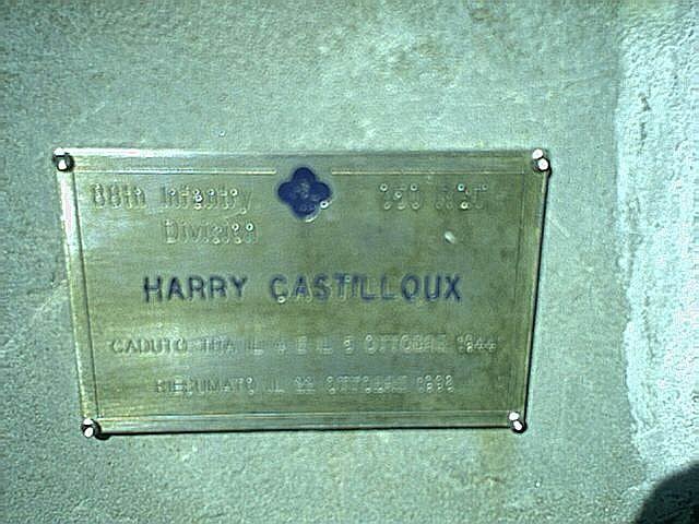
US Soldier: Harry Castilloux was found in 1998
This is Harry Castilloux a Company G 350th Inf soldier
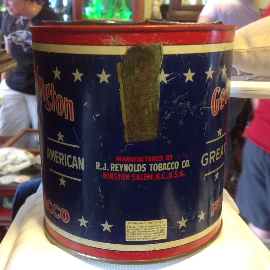
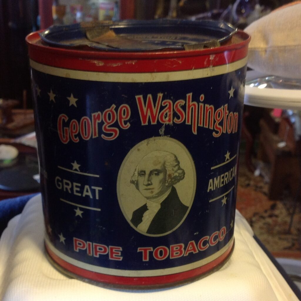
One of the other things I collect is Tobacco Tins. This will just be a page that will outline some information I’ve learned about it.
The George Washington Tobacco tin came in two types. The images below are from 1926 as identified by the tax stamp. This tin has a flat cover. At some point this was changed to be a dome cover (maybe by the early 40s?)